跳转到主内容

Trio Stealth G2 Hype Battery Replacement

你所需要的

  1. Trio Stealth G2 Hype Battery Replacement, Back Panel: 步骤 1 中的图像 1,2 Trio Stealth G2 Hype Battery Replacement, Back Panel: 步骤 1 中的图像 2,2
    • Remove the two 1.2 mm Phillips #0 screws found at the side by the power button.

  2. Trio Stealth G2 Hype Battery Replacement: 步骤 2 中的图像 1,1
    • Using the plastic opening tool, insert it between the back panel and screen starting on the corner to the right of the power button side and begin separating the back cover.

    • Be cautious when opening the back cover as it is connected through fragile wires to the speaker.

  3. Trio Stealth G2 Hype Battery Replacement: 步骤 3 中的图像 1,3 Trio Stealth G2 Hype Battery Replacement: 步骤 3 中的图像 2,3 Trio Stealth G2 Hype Battery Replacement: 步骤 3 中的图像 3,3
    • Remove the speakers by using your hand to entirely disconnect the back cover.

  4. Trio Stealth G2 Hype Battery Replacement, Speakers: 步骤 4 中的图像 1,2 Trio Stealth G2 Hype Battery Replacement, Speakers: 步骤 4 中的图像 2,2
    • Carefully peel the tape holding down the wires connected to the speaker.

  5. Trio Stealth G2 Hype Battery Replacement: 步骤 5 中的图像 1,1
    • In order to replace the speakers after they are removed, you must solder the wires back onto the motherboard.

    • The red wire must be soldered onto the "+" terminal while the black wire must be terminal must be soldered onto the "-" terminal.

    • Pull the speaker and wires from the motherboard.

  6. Trio Stealth G2 Hype Battery Replacement, Battery: 步骤 6 中的图像 1,2 Trio Stealth G2 Hype Battery Replacement, Battery: 步骤 6 中的图像 2,2
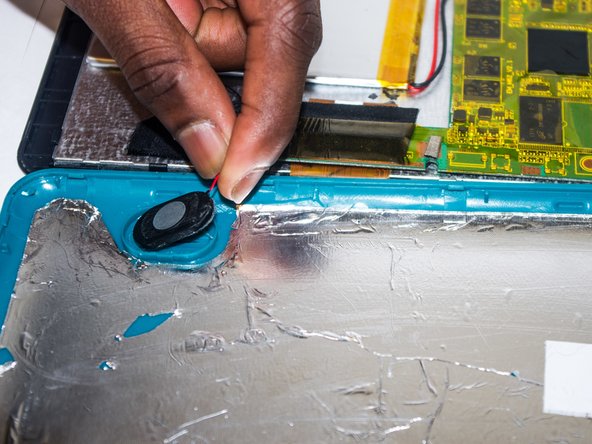
    • While holding the mother board down, slowly remove the battery from tape on the back of the screen.

    • Make sure to keep all wires attached for now.

  7. Trio Stealth G2 Hype Battery Replacement: 步骤 7 中的图像 1,1
    • In order to replace the battery once the wires are removed, you will need to solder the wires of the new battery onto the motherboard.

    • The red wire must be soldered to the "+" terminal while the black is soldered to the "-" terminal.

    • Pull the wires off the motherboard.

结论

To reassemble your device, follow these instructions in reverse order.

2等其他人完成本指南。

团队

USF Tampa, Team 4-4, Brown Winter 2015 USF Tampa, Team 4-4, Brown Winter 2015 的会员

USFT-BROWN-W15S4G4

3 名成员

创作了3篇指南

0条评论

添加评论

浏览统计数据:

过去 24 小时: 0

过去 7 天: 0

过去 30 天: 1

总计 2,292