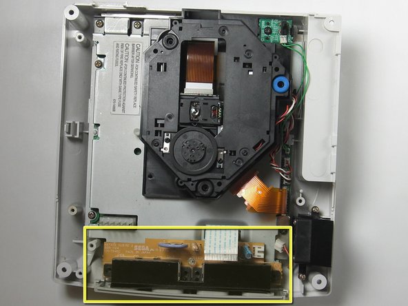
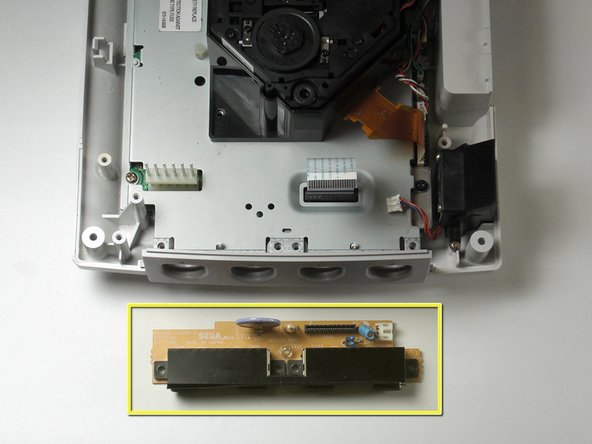
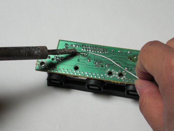
Remove the F1 fuse by using the soldering iron and desoldering wick.
The F1 fuse is clearly indicated on the topside of the controller board.
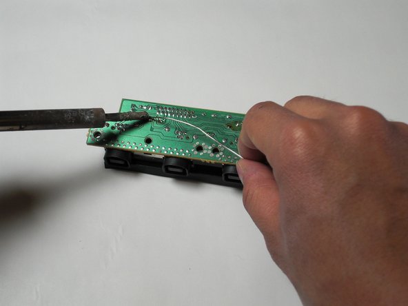
If the F1 through-hole of the circuit board is not visible, you may clean the it by removing the excess solder by using the soldering iron and desoldering wick.
If you are not using a fuse resistor, skip this step. Otherwise, continue.
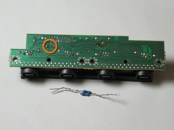
Insert and solder the new fuse resistor to F1 socket.
The fuse resistor should sit on the topside of the board and the leads should be exposed on the underside. Orientation of the fuse resistor does not matter
The 10M 1/2 watt resistor in the picture is used to depict what a fuse resistor might look like.
If you have already used a fuse resistor to complete the previous step, you may omit this step.
Insert and solder the parallel 10 ohm 1/4 watt resistors to the F1 socket.
The resistors should be laid out on the top side of the circuit board and the leads should poke out from the underside. The orientation of the resistor does not matter.
The 1/4 watt resistors shown in the picture are used to depict what parallel resistors should look like.
Verify that the resistor(s) leads do not touch other components on the topside of the circuit board. Otherwise, a short circuit may occur when you power on the system.
Hello, Darren. I am having the utmost difficulty doing this with two 1/4 watt resistors, as you have demonstrated. I have three dreamcast systems, I would like to repair (all with a bad controller port.) What would be the chance that I could send you the ports, packs of resistors and and solder and pay you to do this to all of them?
bonjour Darren. Ma question est surement bête mais est- ce que cette manipulation est nécessaire quand seul le premier port de la Dreamcast ne fonctionne pas ??