你所需要的
-
-
Refer to steps 2-5, 6-7, and 20-21 in the Depth Sensor Node Enclosure Assembly to attach the solar panel to the node enclosure.
-
-
-
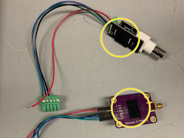
Locate the old style electrically isolated carrier board. If pins are soldered on, remove and solder on a 2 and 3 plug header or one 5-plug header.
-
Once the new attachments are soldered on, proceed to put the temperature circuit board into the connection holes. The black square of the circuit board should face towards the soldered attachments.
-
Refer to the temperature section of the wiring diagram when wiring the adapter.
-
-
-
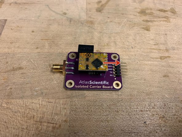
Locate the new style electrically isolated carrier board.
-
Locate the Dissolved Oxygen circuit board and place the board into the connection holes. The black square of the circuit board should face towards the pins.
-
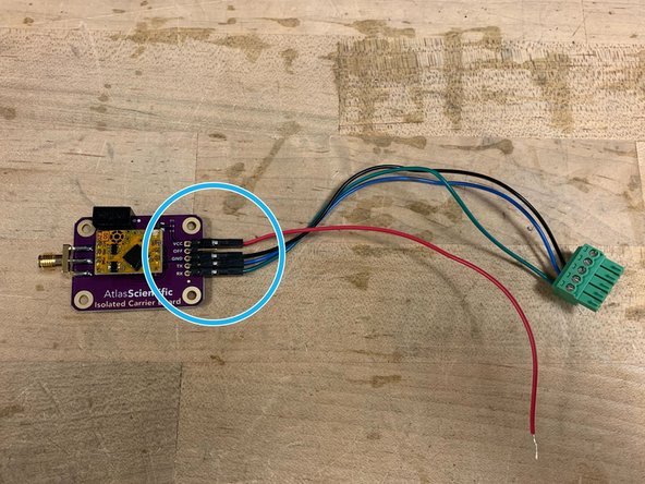
Refer to the DO section of the wiring diagram when wiring the adapter.
-
-
-
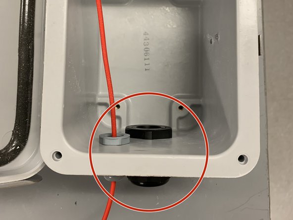
Obtain the cable gland.
-
Screw the cable gland into the wall of the enclosure, through the large hole, as shown.
-
-
-
Insert velcro strips with soft sides inside of the enclosure in the following places
-
Attach velcro with rough side onto the back of the adapters.
-
-
-
Locate the Atlas DO sensor
-
Locate the Atlas PT-1000 Temperature Sensor
-
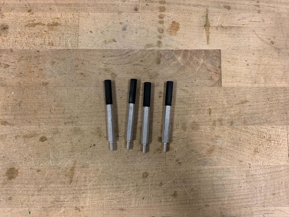
Obtain four 1.5-inch long standoffs and 4 1-inch long standoffs. Screw the standoffs together as shown, to make four 2.5-inch long standoffs
-
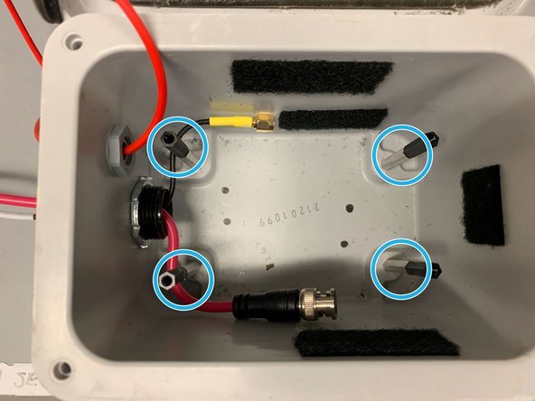
Thread the wires of the sensors into the cable gland. Proceed to screw the standoffs into the holes of the enclosure.
-
-
-
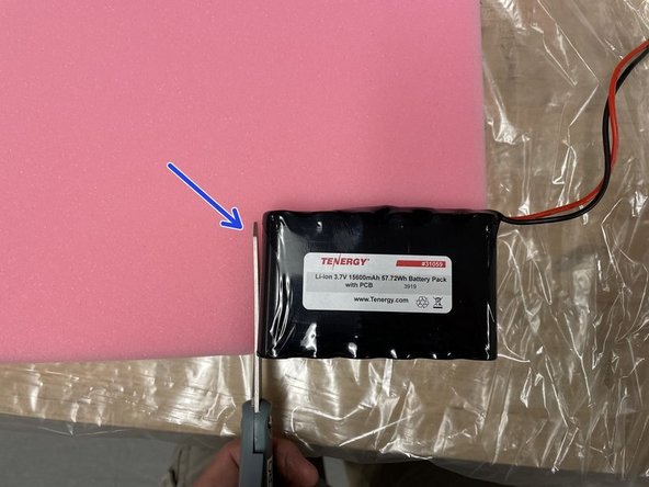
Obtain one battery, 4 zip ties, foam, and a pair of scissors
-
Cut out two battery-sized pieces of foam
-
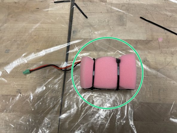
Sandwich the battery between the two pieces of foam and secure it using the zip-ties. Connect the zip-ties to make two extra long zip-ties
-
-
-
-
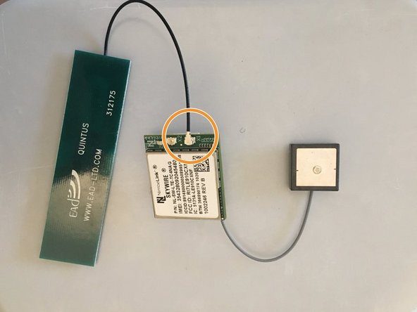
Obtain the cell module (modem), GPS, and antenna
-
Insert Super SIM card into cell module
-
Attach the GPS to the connection shown (grey wire)
-
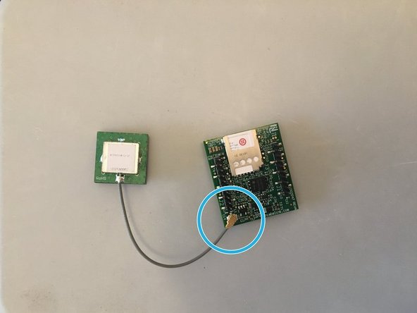
Attach the antenna to the connection shown (black wire)
-
-
-
Attach rough-sided velcro on the antenna and GPS as shown in the picture.
-
-
-
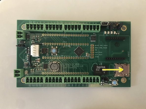
Obtain Open-Storm board and place 4 jumpers in the spots shown
-
Insert microSD card into board
-
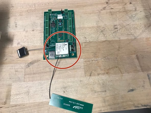
Attach the cellular module onto the sensor node board in the appropriate place
-
-
-
Put the battery into the node enclosure between the area of the standoffs
-
Place the board with the modem and the GPS antenna onto the standoffs and GENTLY screw the board in place. Then stick the modem and GPS in the locations highlighted.
-
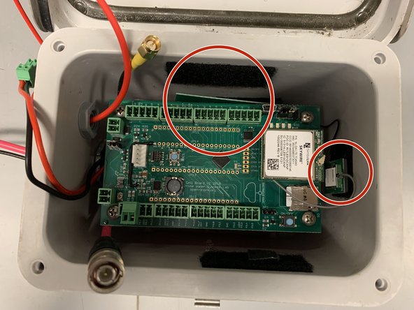
Stick the carrier boards onto the sides of the interior. Make sure to place the carrier in their respective location highlighted.
-
Follow the wiring diagram when wiring the carrier boards to the circuit board.
-
-
-
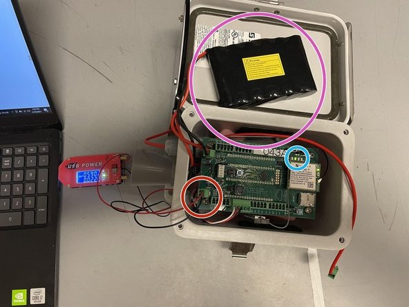
Obtain USB power supply, plug into a laptop, and set output to 5.9V
-
Plug in the green terminal block from the power supply into the Open-Storm board solar port.
-
Confirm the solar charge LED is off.
-
Plug in a dead battery to the battery port. This step will not work with a charged battery
-
CAREFULLY turn the silver potentiometer next to the charge controller IC with a small flathead screw driver until the charge light turns on.
-
-
-
Plug in the battery as highlighted
-
Plug in the solar panel as highlighted
-
The lights of the two sensor circuit boards should turn on
-
-
-
Apply the open-storm sticker to the side of the enclosure as shown
-
Apply the unique node ID sticker to the top as shown
-
-
-
Refer to sections 24-28 of the Depth Sensor Node Assembly guide in constructing and attaching the handle to the node
-
-
-
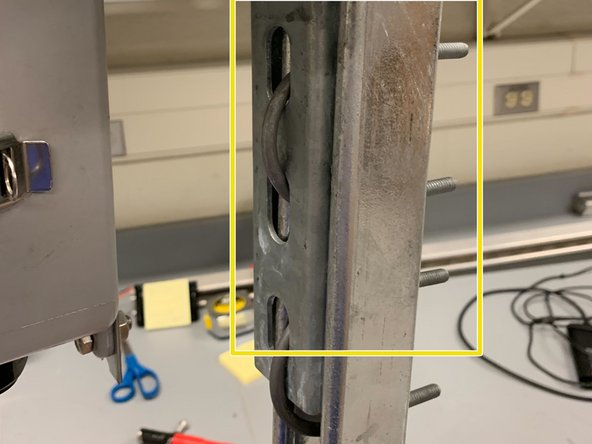
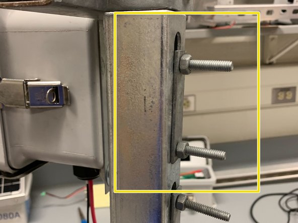
Locate a 5 foot long steel strut channel
-
Using U-bolts, attach the node handle to the strut channel as shown
-
-
-
Using a zip tie, tie both of the sensor's cables together. Since the DO's cable is longer, make a loop to shorten its length
-
Using hose clamps, secure the cables and the sensors along the struct channel
-
-
-
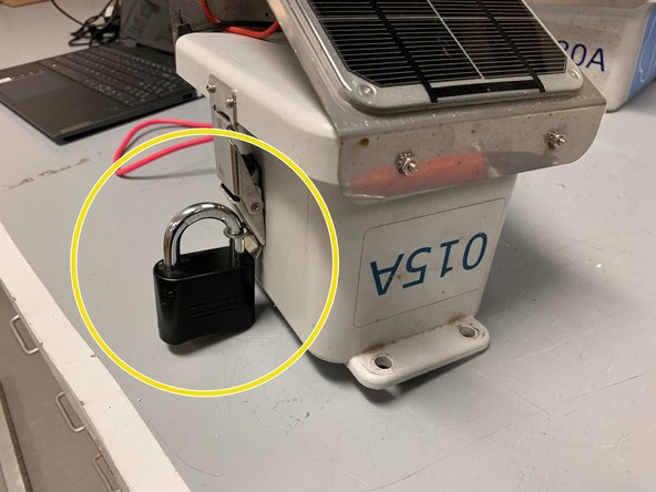
Follow Step 23 of the Depth Node Enclosure Assembly guide to set up the lock
-
-
-
The sensor lights in the node should be turned on
-
Attach the lock to the side of the node
-
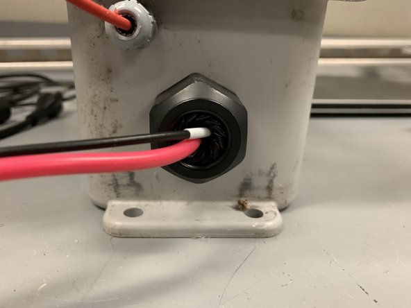
Make sure to twist the cable gland so that the wires are snug together
-
-
-
Make sure the DO circuit board is facing the correct orientation (refer to step 2)
-
Make sure that the jumper wires are connected correctly and securely. Likewise, check if the RX and TX wires are swapped.
-
Check the connection between the adapter cable and the housing of the DO sensor to see if it is tight and sealed.
-
Make sure there is adequate electrolyte solution in the cap of the DO sensor.
-
Replace the DO sensor circuit board.
-


To reassemble your device, follow these instructions in reverse order.
To reassemble your device, follow these instructions in reverse order.
另外一个人完成了本指南。

团队
