简介
This unit provides power to the machine, allows the battery to charge, and provides sound capability.
你所需要的
-
-
Use a coin or a spudger to turn the battery locking screw 90 degrees clockwise.
-
Lift the battery out of the computer.
-
-
-
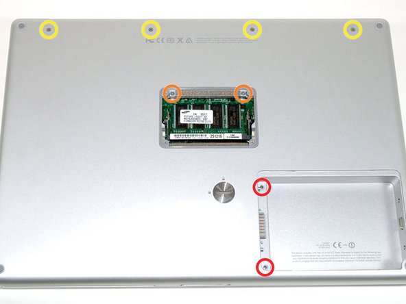
Remove the four Phillips screws from the memory door.
-
Slide the memory door away from the memory compartment.
I recommend that you have several (ie 10-12) little cups nearby with a pen and some small scraps of paper to write on. As you remove screws, step by step, place that step's screws into one cup and label it "Step #X". That way, when you're putting everything back together, you won't have to guess as to which screws were for which step. I did this, on a recommendation of a friend who did this very same repair, and it made the reassembly even easier.
I found that a plastic ice cube tray works best in these situations.
-
-
-
Turn the computer 90 degrees clockwise so that the hinge faces you.
-
Remove the bottom 5 mm Phillips screw on either side of the hinge (two total).
By "bottom", it means the top ones (if the computer were right-side-up), i.e. the ones closer to the lid.
-
-
-
Rotate the computer 90 degrees clockwise, so that the ports face you.
-
Remove the three 3 mm Phillips screws.
Don't be hasty! I've seen 2 laptops with a forlorn screw trapped in a video port screwhole, from where it's very difficult, if not impracticable, to remove it.
-
-
-
Grasp the back corners of the upper case and pull up. Do not pull the upper case off yet; you still need to disconnect the keyboard and trackpad cable.
-
Lift the back of the case up and work your fingers along the sides, freeing the case as you go. Once you have freed the sides, you may need to rock the case up and down to free the front of the upper case.
-
-
-
Rotate the upper case up and toward the screen, so that the upper case rests against it.
For this stage I found Step 9 and Step 10 in the guide for Hard Drive replacement were helpful in expanding on removal of top cover. See link here : PowerBook G4 Aluminum 15" 1-1.5 GHz Hard Drive Replacement
-
-
-
Remove the 9.5 mm silver Phillips screw from the top of the right ambient light sensor board.
-
Remove the small 3 mm black Phillips screw from the bottom of the board.
-
-
-
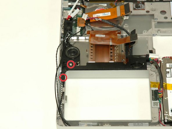
Remove the two black Phillips screws from the right speaker.
-
Lift the speaker away from the logic board and place it aside
-
-
-
-
Disconnect the DC-In connector from the left side of the logic board.
It may be easier to disconnect the DC-in connector from the DC-Sound board end of the connector rather than from the logic board side of the connector
-
-
-
Grasp the logic board at the left edge with one hand and at the thinnest section with the other hand. Lift the left edge of the board up to approximately a 30 degree angle (if you don't have your protractor handy, just lift until the DVI port clears the right hinge).
-
Once the logic board clears the ports, slide it out to the left.
Great guide! Fantastic idea in the comments to print the instructions and then tape the screws by the step as you go. I found that it was easier to remove the screen and hinges before taking out the logic board. It made it much easier to remove and replace the right side of the logic board.
-
-
-
To properly reassemble your PowerBook, you'll have to clean off and replace the old thermal compound. Use our Applying Thermal Paste Guide to prepare the processor and heat sink surfaces.
-
-
-
Remove the two 3 mm black Phillips screws from the left ambient light sensor board.
-
Lift the left ambient light sensor board out of the computer, removing tape as necessary.
-
-
-
Remove the two 4.2 mm silver Phillips screws from the left corners of the PC card cage.
-
-
-
Remove the two 4.2 mm silver Phillips screws from either side of the large orange Airport ribbon.
-
-
-
Lift the Airport card out of the computer and slide a spudger between the card and the antenna connector to disconnect the cable from the card.
-
Deroute the antenna cable from the side of the card, removing tape as necessary.
-
You don't need to remove the Airport card entirely. We're just trying to free up the Airport antenna cable.
-
-
-
Close the display and turn the hinge side of the computer to face you.
-
Remove the remaining Phillips screw on either side of the hinge (two screws total).
-
-
-
Open the display and turn the computer so the screen faces you.
-
Remove the 10 mm T8 Torx screw closer to the display on either side of the hinge (two screws total).
Ground loop goes on T8 Torx screw nearest the display
The ground loop attaches with the T8 Torx screw nearest the display
-
-
-
Remove the following 7 Phillips screws from the heat sink:
-
Four 4 mm silver screws.
-
Two 5 mm black screws.
-
One 9 mm silver screw in the upper left corner of the left fan.
-
-
-
Remove the heat sink from the case, minding the left corner, as it tends to catch in the case (the fans will come out with the heat sink).
When the heat sink is removed, notice that there are two, black plastic spacers on the upper side and two more on the lower side. These are located about 1.5" (3.5cm) inboard of the two fans, on the edge nearest the hinge. You can see the upper ones in the photo. I believe they are glued in place but then glue can break and the spacers fall out. You need to put them back in.
-
-
-
Use your thumbs to slide the RJ-11 board away from the sound card in the same direction you would disconnect a cable. This is your chance to get out some aggression, as the board will most likely be very tight and requires a good deal of force to remove. Don't get carried away though - don't hold onto the power connector and don't put too much actual force on the card itself.
-
The DC/Sound card should now be free.
-


To reassemble your device, follow these instructions in reverse order.
To reassemble your device, follow these instructions in reverse order.
16等其他人完成本指南。
附加文件

3条评论
The Tools Used list specifies a #6 Torx wrench, but in step 7 it says a 1.5mm hex wrench is preferred. This is good to know ahead of time since a #6 Torx wrench is not available from the local hardware store, but a 1.5mm hex wrench is.
Thermal paste is required for reassembly at step 17.
I follow the instruction to open the box, but you don't have to take the whole computer apart to get to the part. You can work on the side where the part is and it is much more easier. The chance of breaking a wire is less likely. I recommend that once the box is open and the mainboard is exposed, that the person on unscrew the left speakers, remove the screw near the small left speaker. Remove the screws that secure the PC Card tray, remove the tray. Remove the screws that secure the electronic eye to the top left, remove the screw that secure the dc board and the parts is ready to come out.
Agreed - I just removed the DC/sound board without touching the logic board! very happy =)
JP
Jesal -