跳转到主内容

当前版本的文档还未经巡查,您可以查看最新的已查核版本

你所需要的

  1. , 拆开外壳: 步骤 1 中的图像 1,2 , 拆开外壳: 步骤 1 中的图像 2,2
    • 关闭电源并且移除记忆卡

    • 用一个Phillips #00 规格的螺丝刀除下后壳上4 个 6.4mm 规格的螺丝。

  2. : 步骤 2 中的图像 1,3 : 步骤 2 中的图像 2,3 : 步骤 2 中的图像 3,3
    • 使用指甲或者撬棒,撬开设备顶部的附件端口盖。

    • 使用 Phillips #00 规格的螺丝刀,移除隐藏在附件端口盖下面的 2 个 5.4mm 规格螺丝。

  3. : 步骤 3 中的图像 1,2 : 步骤 3 中的图像 2,2
    • 移除设备底部充电端口旁边的 2 个 5.4mm Phillips #00 规格的螺丝 。

  4. : 步骤 4 中的图像 1,3 : 步骤 4 中的图像 2,3 : 步骤 4 中的图像 3,3
    • 从设备两侧开始,使用塑料开启工具来分离前盖和后盖。

    • 继续用这个方式沿着设备轻轻地撬开它。

    • 需要注意的是,前壳和后壳之间有电线连接,如果您将外壳完全分开,可能会损坏连接线。

  5. : 步骤 5 中的图像 1,2 : 步骤 5 中的图像 2,2
    • 轻缓地将前壳和后壳分离,注意电池和触摸屏幕控制器的接口保持连接。

  6. : 步骤 6 中的图像 1,1
    • 使用撬棒,轻轻地将触摸屏控制器线缆撬起。

  7. : 步骤 7 中的图像 1,1
    • 用撬棒将电池连接线轻轻撬起。

  8. : 步骤 8 中的图像 1,1
    • 分开前后壳。

  9. 这个步骤还没有翻译 帮忙翻译一下

    : 步骤 9 中的图像 1,3 : 步骤 9 中的图像 2,3 : 步骤 9 中的图像 3,3
    • Using the pointy end of the spudger, disconnect the three antenna cable connectors on top of the wireless card.

    • Deroute the antenna cables so that they are out of the wireless card casing. Rest the wires out of the way.

  10. 这个步骤还没有翻译 帮忙翻译一下

    : 步骤 10 中的图像 1,2 : 步骤 10 中的图像 2,2
    • Hook the spudger beneath the tab on the wireless card casing and release the tab.

    • Peel up and remove the wireless card casing.

  11. 这个步骤还没有翻译 帮忙翻译一下

    : 步骤 11 中的图像 1,2 : 步骤 11 中的图像 2,2
    • Remove the two 4.4mm Phillips #00 screws on the wireless card.

    • The wireless card will naturally pop out at an angle.

    • Pull out the wireless card.

  12. 这个步骤还没有翻译 帮忙翻译一下

    : 步骤 12 中的图像 1,3 : 步骤 12 中的图像 2,3 : 步骤 12 中的图像 3,3
    • Pry up the right shoulder button casing with a spudger and set it aside.

  13. 这个步骤还没有翻译 帮忙翻译一下

    : 步骤 13 中的图像 1,1
    • Remove the translucent, plastic right shoulder button cover.

  14. 这个步骤还没有翻译 帮忙翻译一下

    : 步骤 14 中的图像 1,3 : 步骤 14 中的图像 2,3 : 步骤 14 中的图像 3,3
    • Release the right shoulder button flex cable socket by using a spudger to gently pry open the tab.

    • Using tweezers, slide the flex cable out of the socket.

  15. 这个步骤还没有翻译 帮忙翻译一下

    : 步骤 15 中的图像 1,2 : 步骤 15 中的图像 2,2
    • Using a spudger, gently peel up the right shoulder button from the light adhesive connecting it to casing.

  16. 这个步骤还没有翻译 帮忙翻译一下

    : 步骤 16 中的图像 1,2 : 步骤 16 中的图像 2,2
    • Using the pointy end of a spudger, detach the antenna cable on the right button board.

    • Remove the antenna cable.

  17. 这个步骤还没有翻译 帮忙翻译一下

    : 步骤 17 中的图像 1,2 : 步骤 17 中的图像 2,2
    • Using a spudger, pry up and release the ZIF socket on the right button board.

    • Gently pull the flex cable out of the socket. Rest the flex cable out of the way.

  18. 这个步骤还没有翻译 帮忙翻译一下

    : 步骤 18 中的图像 1,3 : 步骤 18 中的图像 2,3 : 步骤 18 中的图像 3,3
    • Release the tab on the small flex cable socket by prying up the tab with a spudger.

    • Using tweezers, gently pull the flex cable out of the socket. Rest the flex cable out of the way.

  19. 这个步骤还没有翻译 帮忙翻译一下

    : 步骤 19 中的图像 1,3 : 步骤 19 中的图像 2,3 : 步骤 19 中的图像 3,3
    • Remove the two 5.0mm Phillips #00 screws from the metal bracket securing the right button board to the motherboard.

    • Remove the metal bracket, using a spudger as necessary to lift it out.

  20. 这个步骤还没有翻译 帮忙翻译一下

    : 步骤 20 中的图像 1,3 : 步骤 20 中的图像 2,3 : 步骤 20 中的图像 3,3
    • Use a spudger to free the right button board by prying up from the bottom right corner of board.

    • Gently lift the right button board out.

  21. 这个步骤还没有翻译 帮忙翻译一下

    : 步骤 21 中的图像 1,3 : 步骤 21 中的图像 2,3 : 步骤 21 中的图像 3,3
    • Pry up the left shoulder button casing with a spudger.

    • Remove the left shoulder button casing.

  22. 这个步骤还没有翻译 帮忙翻译一下

    : 步骤 22 中的图像 1,2 : 步骤 22 中的图像 2,2
    • Remove the translucent, plastic left shoulder button cover.

  23. 这个步骤还没有翻译 帮忙翻译一下

    : 步骤 23 中的图像 1,3 : 步骤 23 中的图像 2,3 : 步骤 23 中的图像 3,3
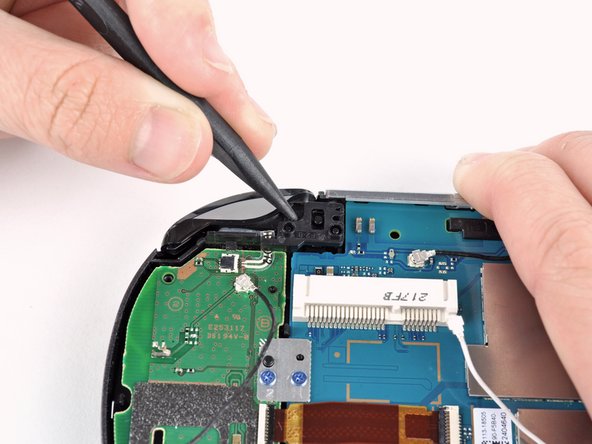
    • Release the left shoulder button flex cable socket by using a spudger to pry open the tab.

    • Be careful to not break off this small black tab!

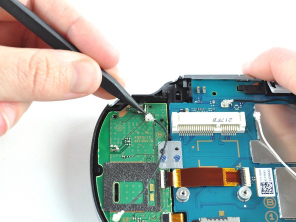
    • Using tweezers, slide the flex cable out of the socket. Do not pull on the black tab! Instead, pull the thin flex cable away from the connector (to the left in this image).

  24. 这个步骤还没有翻译 帮忙翻译一下

    : 步骤 24 中的图像 1,2 : 步骤 24 中的图像 2,2
    • Using a spudger, gently peel up the left shoulder button from the light adhesive connecting it to casing.

  25. 这个步骤还没有翻译 帮忙翻译一下

    : 步骤 25 中的图像 1,2 : 步骤 25 中的图像 2,2
    • Using a spudger, lift and release the tab on the ZIF socket sitting on the SIM card reader.

    • Carefully pull the flex cable out of the ZIF socket, and rest it out of the way.

  26. 这个步骤还没有翻译 帮忙翻译一下

    : 步骤 26 中的图像 1,3 : 步骤 26 中的图像 2,3 : 步骤 26 中的图像 3,3
    • Use a spudger to release the tab between the SIM card reader and the back casing assembly.

    • Lift the SIM card reader off the back casing assembly.

  27. 这个步骤还没有翻译 帮忙翻译一下

    : 步骤 27 中的图像 1,2 : 步骤 27 中的图像 2,2
    • Release the plastic tab on the small flex cable socket by prying it up with a spudger.

    • Using tweezers, gently remove the small flex cable from the socket, and rest it out of the way.

  28. 这个步骤还没有翻译 帮忙翻译一下

    : 步骤 28 中的图像 1,2 : 步骤 28 中的图像 2,2
    • Use a spudger to lift up the tab on the large ZIF socket.

    • Gently pull the flex cable out of the ZIF socket, and rest it out of the way.

  29. 这个步骤还没有翻译 帮忙翻译一下

    : 步骤 29 中的图像 1,2 : 步骤 29 中的图像 2,2
    • Disconnect the white Wi-Fi antenna cable with a spudger.

    • Remove the Wi-Fi antenna cable.

  30. 这个步骤还没有翻译 帮忙翻译一下

    : 步骤 30 中的图像 1,3 : 步骤 30 中的图像 2,3 : 步骤 30 中的图像 3,3
    • Using a Phillips #00 screwdriver, remove the six screws on the two metal brackets:

    • Two 5.0mm, blue screws on the L-bracket securing the upper left button board to the motherboard.

    • Four 5.0mm, blue screws on the square bracket securing the lower left button board to the motherboard.

  31. 这个步骤还没有翻译 帮忙翻译一下

    : 步骤 31 中的图像 1,3 : 步骤 31 中的图像 2,3 : 步骤 31 中的图像 3,3
    • Starting from the upper left corner, use a spudger to pry up and remove the left button board.

  32. 这个步骤还没有翻译 帮忙翻译一下

    : 步骤 32 中的图像 1,2 : 步骤 32 中的图像 2,2
    • Using the pointy end of a spudger, pry up and release the GPS antenna cable from the motherboard.

    • Remove the GPS antenna cable.

  33. 这个步骤还没有翻译 帮忙翻译一下

    : 步骤 33 中的图像 1,2 : 步骤 33 中的图像 2,2
    • Release the camera flex cable socket by prying up on the tab with a spudger.

  34. 这个步骤还没有翻译 帮忙翻译一下

    : 步骤 34 中的图像 1,2 : 步骤 34 中的图像 2,2
    • Using a spudger, gently pry up on the camera.

    • Work your way under the camera and along the camera flex cable, using the spudger to peel away the adhesive, freeing the camera.

  35. 这个步骤还没有翻译 帮忙翻译一下

    : 步骤 35 中的图像 1,2 : 步骤 35 中的图像 2,2
    • Carefully lift and remove the camera, sliding the flex cable out of the open connector socket.

  36. 这个步骤还没有翻译 帮忙翻译一下

    : 步骤 36 中的图像 1,2 : 步骤 36 中的图像 2,2
    • Using a Phillips #00 screwdriver, remove the 6.3mm screw beneath the camera.

    • Lift and remove the metal camera bracket.

  37. 这个步骤还没有翻译 帮忙翻译一下

    : 步骤 37 中的图像 1,2 : 步骤 37 中的图像 2,2
    • With the help of a spudger, lift and release the tab on the blue flex cable socket.

  38. 这个步骤还没有翻译 帮忙翻译一下

    : 步骤 38 中的图像 1,2 : 步骤 38 中的图像 2,2
    • Using tweezers, gently pull the blue power flex cable out of the socket; rest it out of the way.

  39. 这个步骤还没有翻译 帮忙翻译一下

    : 步骤 39 中的图像 1,1
    • Using a Phillips #00 screwdriver, remove the two pink, 4.4mm screws securing the motherboard.

  40. 这个步骤还没有翻译 帮忙翻译一下

    : 步骤 40 中的图像 1,3 : 步骤 40 中的图像 2,3 : 步骤 40 中的图像 3,3
    • Gently peel the rubber tab of the game port cover off the plastic casing pins.

    • Remove the game port cover.

  41. 这个步骤还没有翻译 帮忙翻译一下

    : 步骤 41 中的图像 1,3 : 步骤 41 中的图像 2,3 : 步骤 41 中的图像 3,3
    • Gently peel the rubber tab of the accessory port cover off the plastic casing pins.

    • Remove the accessory port cover.

  42. 这个步骤还没有翻译 帮忙翻译一下

    : 步骤 42 中的图像 1,3 : 步骤 42 中的图像 2,3 : 步骤 42 中的图像 3,3
    • Starting at the upper right hand corner, use a spudger to gently lift the motherboard out of the casing assembly.

    • The motherboard is still attached to the casing by a connector on the back of the motherboard. Do not pull the motherboard all the way out, or you may damage the connector.

  43. 这个步骤还没有翻译 帮忙翻译一下

    : 步骤 43 中的图像 1,3 : 步骤 43 中的图像 2,3 : 步骤 43 中的图像 3,3
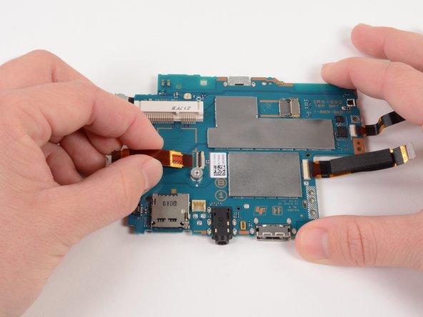
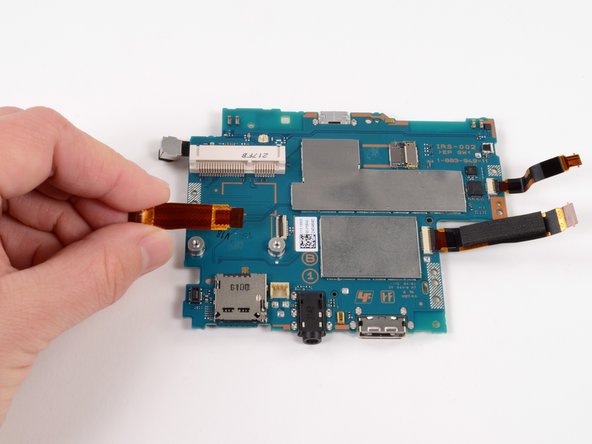
    • Lift the motherboard out and identify the OLED connector still attaching the motherboard to the casing.

    • Holding the Vita on its side, use a spudger to gently pry off the OLED connector from the motherboard.

    • Be sure to hold the motherboard while you release the connector as this will free the motherboard. If you are not holding the motherboard, it will fall.

  44. 这个步骤还没有翻译 帮忙翻译一下

    : 步骤 44 中的图像 1,1
    • Completely separate the motherboard from the case. Remove the case.

  45. 这个步骤还没有翻译 帮忙翻译一下

    : 步骤 45 中的图像 1,3 : 步骤 45 中的图像 2,3 : 步骤 45 中的图像 3,3
    • Starting at the right side, gently lift and remove the black casing that once held the camera.

  46. 这个步骤还没有翻译 帮忙翻译一下

    : 步骤 46 中的图像 1,2 : 步骤 46 中的图像 2,2
    • Using a spudger, release the tab on the ZIF connector located above the two screw posts where the wireless card once was.

  47. 这个步骤还没有翻译 帮忙翻译一下

    : 步骤 47 中的图像 1,3 : 步骤 47 中的图像 2,3 : 步骤 47 中的图像 3,3
    • Gently pull the flex cable out of the ZIF connector, and remove it.

  48. 这个步骤还没有翻译 帮忙翻译一下

    : 步骤 48 中的图像 1,2 : 步骤 48 中的图像 2,2
    • Release the tab on the large ZIF connector on the right side of the motherboard by lifting the tab with a spudger.

  49. 这个步骤还没有翻译 帮忙翻译一下

    : 步骤 49 中的图像 1,2 : 步骤 49 中的图像 2,2
    • Gently pull the flex cable out of the ZIF connector, and remove it.

  50. 这个步骤还没有翻译 帮忙翻译一下

    : 步骤 50 中的图像 1,2 : 步骤 50 中的图像 2,2
    • Using a spudger, release the small ZIF connector on the right side of the motherboard.

  51. 这个步骤还没有翻译 帮忙翻译一下

    : 步骤 51 中的图像 1,3 : 步骤 51 中的图像 2,3 : 步骤 51 中的图像 3,3
    • Gently pull the flex cable out of the small ZIF connector, and remove it.

  52. 这个步骤还没有翻译 帮忙翻译一下

    : 步骤 52 中的图像 1,2 : 步骤 52 中的图像 2,2
    • Flip the motherboard over.

    • With the help of a spudger, pry up and release the tab of the rear camera flex cable connector.

  53. 这个步骤还没有翻译 帮忙翻译一下

    : 步骤 53 中的图像 1,3 : 步骤 53 中的图像 2,3 : 步骤 53 中的图像 3,3
    • Gently pull the rear camera out of the connector and remove it.

  54. 这个步骤还没有翻译 帮忙翻译一下

    : 步骤 54 中的图像 1,1
    • The motherboard remains.

终点

41等其他人完成本指南。

Brittany McCrigler

于03/05/12注册

89,017 声望

创作了131篇指南

团队

iFixit iFixit 的会员

Staff

135 名成员

创作了16,817篇指南

11条评论

in steps 2&3, bottom is top and top is bottom

Samir Al Jubori - 回复

it should be noted that the memory card should always be taken out before separating the case. I just broke my memory card slot by having a card in there while I was opening the case, there's a tiny bit of overhang that will pull the slot off the motherboard.

bryandodson - 回复

does anyone know what firmware version the motherboard comes with?

riddochj - 回复

These are used Motherboards. You could get a motherboards with a random FW version.

Raheem -

Okay My original Motherboard power connector broke. So nothing was wrong with it except the Power connector.

My first buy of the Motherboard screen connector broke off.

The Replacement works well, however the Touch input isn't working, unless I restore the device. After a certain amount of time it becomes unresponsive.

Do anyone have a fix before I get a 3rd replacement.

Raheem - 回复

添加评论

浏览统计数据:

过去 24 小时: 13

过去 7 天: 68

过去 30 天: 302

总计 63,610