简介
Panasonic DMC-FZ35 Top Control Panel Replacement
你所需要的
-
-
Remove 1 screw (0.4mm) from left side of unit
-
Remove 1 screw (0.4mm) from right side of unit near Strap bar.
-
Remove 1 screw (0.6mm) from right side of unit next to usb door
-
-
-
Remove 3 Screws from bottom of unit
-
Remove 2 (0.6mm) screws next to door
-
Remove 1 (0.4mm) screw opposite of door
-
-
-
Raise the Pop-Up flash by pushing the flash button.
-
Remove the screw (0.6mm) from underneath the flash assembly.
-
-
-
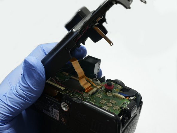
Lift the cover slightly as shown in picture # 1
-
Tilt the back cover as shown in picture #2. Be careful because the flex cables are still attached.
-
-
-
Flip up LCD cable clamp with a spudger or other tool.
-
Flip up backlite cable clamp with a spudger or other tool
-
Removal of the mic wire is optional. My suggestion is to leave it attached. The mic can get damaged if you pull on the wire.
-
-
-
-
Remove the 2 screws (0.4mm) that are holding the mic assembly
-
Next step (shown in picture #2) remove the metal mic hold part.
-
Next step (shown in picture #3) use a spudger to pry off the mic. Careful not to damage the wiring.
-
-
-
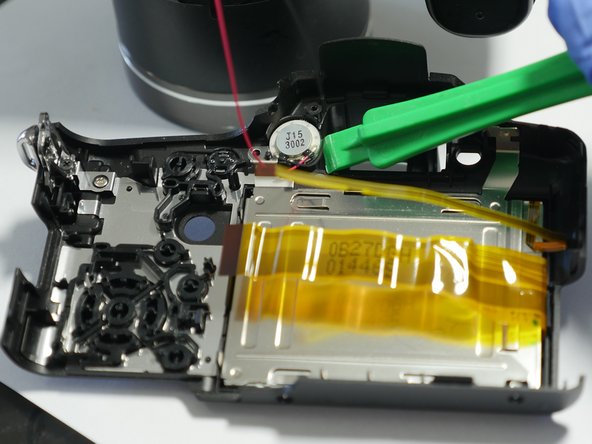
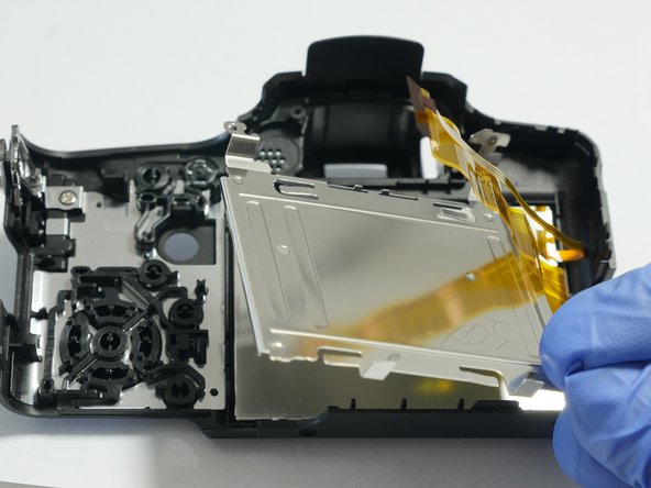
Release the hold clips that hold the LCD retainer in place.
-
Remove the LCD metal retainer plate as shown in picture #2
-
Remove the LCD as shown in picture # 3
-
-
-
Swap out your old LCD with the new one.
-
If your backlite is ok you can buy only the LCD Display. But it is easier to purchase the LCD with the backlite attached. Replacement LCD Display VYQ5034
-
-
-
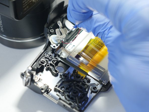
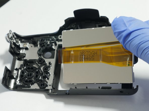
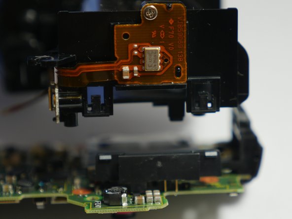
Pull the 3 flex cables out using flat needle nose pliers (it is easier to slide open the black clamps prior to pulling). These are sliding clamps not flip (up) clamps.
-
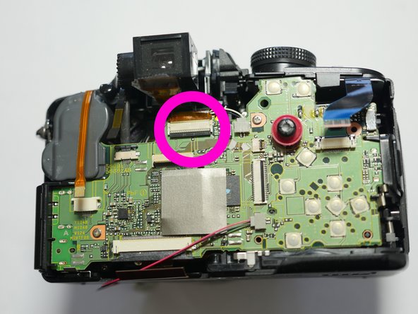
Pull the single cable from the socket. This is a friction fit socket.
-
Flip up the Cable clamp (picture #2) using a spudger as shown in the previous pages and release the cable.
-
Flip up the Cable Clamp (picture #3) using a spudger and release the cable.
-
-
-
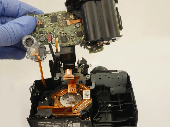
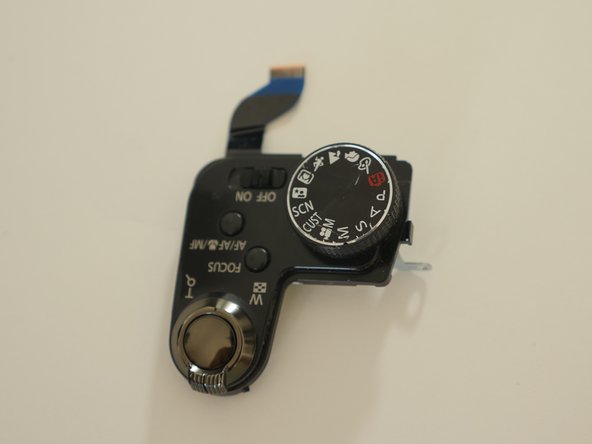
Release the socket. It would be best to use a method that does not require pulling on the wires.
-
One way to release the socket is by carefully inserting a thin wedge between the male and female sockets and carefully pry them apart.
-
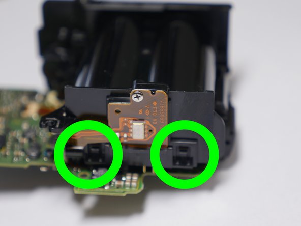
Remove 1 silver screw (0.4mm) next to joy stick.
-
Remove 1 silver blue tip coated (0.4mm) screw bottom left corner.
-


To reassemble your device, follow these instructions in reverse order.
To reassemble your device, follow these instructions in reverse order.
另外一个人完成了本指南。
2条评论
Is it possible to remove the Top control panel without removing the main PCB ?
Required parts no longer for sale