简介
This guide shows how to access and if necessary remove the IR board. This is most often done primarily to solder on a header to reprogram the IR driver microcontroller to improve the IR positional tracking performance. It forms a part of the overall instructions to reprogram the IR driver microcontroller.
This guide is included as a "prerequisite" to the Technique: How to add a IR board programming connector to OSVR HDK 1.2 1.3 1.4 2 guide, so if that's what you want to do, that's the only guide you need to follow, it includes all the steps here.
Portions of this guide are based on other community-contributed iFixit guides for the HDK - thank you to those contributors for their work, especially their great photography! Their disclaimer applies to this as well, of course: they are not responsible if you break anything following this guide.
你所需要的
-
-
Lay HDK headset face down on a soft surface. Remove the two Phillips #00 screws from the bottom.
-
-
-
Turn the headset upright.
-
Behind the red box is a connector between a ribbon cable attached to the faceplate and a ribbon cable wrapped inside the body of the HMD. It's taped together in addition to the force of the connection, but is still somewhat fragile, so when opening, this left side should be treated as the "hinge".
-
There are now only two pairs of magnets at the top in the corners holding the faceplate to the body of the HMD. (In the inside image, one of the faceplate magnets is not pictured.)
-
There are two grooves on top, marked, to use in faceplate removal. Keeping in mind the minimal force holding the faceplate on, and the location of the faceplate connector, gently pull/fold the faceplate out and to the left. Do not use any tools for this step!
-
-
-
-
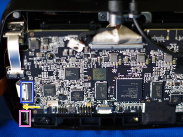
If you are following this guide to reprogram the IR board, and are able to use the "P5" programming connector - no more disassembly is required. The pink box indicates the location of P5 in an assembled HDK 1.x with the connector (1.4 units shipped with a P5-containing IR board).
-
Disconnect the board-to-board ribbon cable (connecting the IR board to the main circuit board) by lifting/tilting the white locking piece then gently sliding out the ribbon cable.
-
Flat on the surface of the IR board, about where the yellow arrow points, the orange ribbon cables (which carry the IR LEDs and additional positional tracking circuitry) connect to the IR board with the same sort of flat connector that is used between the faceplate ribbon cable and the main body.
-
The connector section of the ribbon cable is reinforced with a small board, which you can see just past the edge of the IR board itself. In a 1.4 or newer, as shown, it's right above the P5 connector (pink). If you come in from the front, you'll likely need a fingernail or pick/spudger. From behind the connector, a finger will probably be enough.
-
Once those two cables have been removed, you should be able to shimmy the IR board out: be careful not to tug on any of the orange ribbon cables (they should be attached to the HMD case with adhesive on rubber bumpers at each LED location). It's OK to press the rubber bumpers back down onto the case if the adhesive has pulled away.
-
-
-
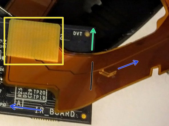
First photo: connector attached, with ribbon cable unfolded out of the way for a clear view. Viewing the "top" of the board, which faces out the side of the HMD when installed.
-
When inside the HDK, the green arrow would be pointing out the front of the HMD.
-
When the orange ribbon cable with the LEDs is correctly left intact, it would actually gently bend (near the marked black line) over the IR board so that both blue arrows would point toward the top of the HMD.
-
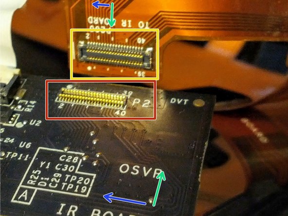
Second image: connector immediately after disconnection, with both halves of the connector facing the camera. Again, ribbon cable unnaturally unfolded for ease of photography. As before, green arrows would point out the front, and blue arrows would point toward the top.
-
Here, you can see both the ribbon-cable side of the connector ("receptacle"), in yellow, and the board-side connector, highlighted in red. For a clearer view of how they mate, see the JAE WP7 series connector datasheet (board uses a JAE-WP7B-P040VA1) which has 3d renderings.
-
-
-
Here you can get a better look at the features from the previous step which may help in reassembly.
-
This is the board-to-board ribbon cable. Removing the main board end is much easier to re-assemble than removing the IR board end, so just leave this cable attached to the IR board while it's out.
-
This is the board half of the connector to the orange ribbon cables - you can see it's flat against the board and rectangular in shape (and not necessarily perfectly square with the board), which might help you visualize reconnecting it.
-
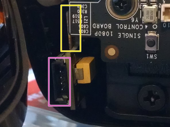
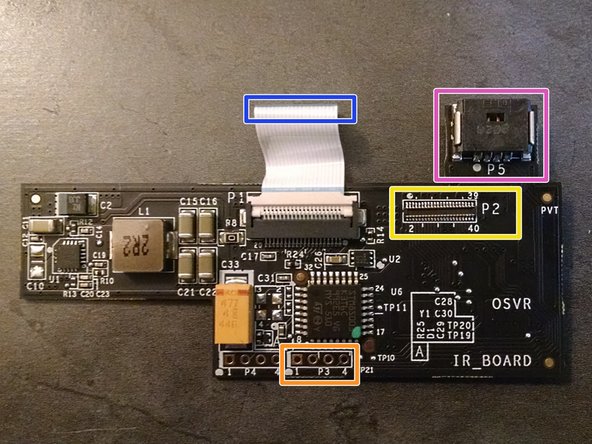
This is the "P5" programming header suitable for use with official, full ST-Link v2 kits with cable bundle. Earlier boards do not have this connector or even this section of circuit board jutting out - that's nothing to worry about. The pinout is a duplicate of P3.
-
At the bottom-center, below the STM8 microcontroller, is a pair of unpopulated headers. The P3 header, highlighted in orange, is the programming header, and thus the one we're interested in. Pin 1 and 4 are numbered in the silkscreen, and pin 1 is also marked with a dot and has a square, rather than circular, pad.
-
If your P3 and P4 headers are populated with terminated wires (some early 1.2 units only), you can use the wires directly. See the next step. Otherwise, skip it.
-
-
-
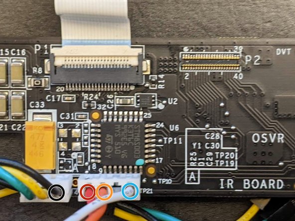
If your P3 and P4 headers are populated with terminated wires (some early 1.2 units only), you can use the wires directly. You'll need these wires:
-
GND: Third wire (black) from the first header (P4)
-
3.3V: First wire (red), P3
-
SWIM: Second wire (orange), P3
-
RESET: Third wire (fourth pin, white), P3
-


To reassemble your device, follow these instructions in reverse order. If you added a header on a cable, fold it in carefully, and be sure to not disturb the location of the rubber bumpers and LEDs on the IR ribbon cables. Give the connector to the faceplate ribbon cable a gentle squeeze to make sure it has stayed connected.
To reassemble your device, follow these instructions in reverse order. If you added a header on a cable, fold it in carefully, and be sure to not disturb the location of the rubber bumpers and LEDs on the IR ribbon cables. Give the connector to the faceplate ribbon cable a gentle squeeze to make sure it has stayed connected.
另外一个人完成了本指南。
