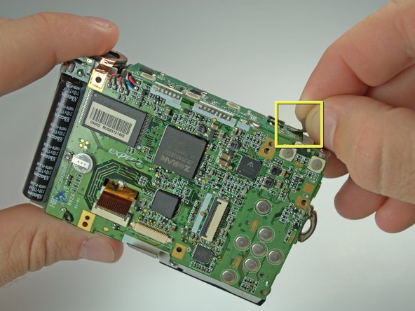
跳转到主内容

Nikon Coolpix L18 Logic Board Replacement

你所需要的

  1. Nikon Coolpix L18 Logic Board Replacement, Back Cover: 步骤 1 中的图像 1,1
    • Remove the memory stick from the camera.

    • Remove the batteries from the camera.

  2. Nikon Coolpix L18 Logic Board Replacement: 步骤 2 中的图像 1,2 Nikon Coolpix L18 Logic Board Replacement: 步骤 2 中的图像 2,2
    • Remove all six 4.3mm silver screws along the perimeter of the camera using the Phillips #00 screwdriver.

    • There is one screw hidden under the AV cover that also needs to be removed.

  3. Nikon Coolpix L18 Logic Board Replacement: 步骤 3 中的图像 1,1
    • Pry the back cover from the left side of the camera. Remove the cover gently.

  4. Nikon Coolpix L18 Logic Board Replacement, Front Cover: 步骤 4 中的图像 1,1
    • Pry back the front cover of the camera starting from the right side.

  5. Nikon Coolpix L18 Logic Board Replacement, LCD Screen: 步骤 5 中的图像 1,1
    • This is where energy for the flash is stored. Even with batteries removed, if you touch these connections, you can be shocked, depending on if the flash capacitor has a stored charge. It may not have a stored charge, but work around this assuming it does.

    • Newer cameras of decent quality usually have a bleeder resistor to drain the flash capacitor. This may not work anymore and the flash capacitor may still have a charge.

  6. Nikon Coolpix L18 Logic Board Replacement: 步骤 6 中的图像 1,1
    • Remove the tape on the right side of the LCD screen.

    • Gently lift the LCD screen from its base.

    • Don't tug on the screen because it is still connected to the motherboard.

  7. Nikon Coolpix L18 Logic Board Replacement: 步骤 7 中的图像 1,1
    • Lift the black latch connecting the LCD ribbon to the motherboard.

    • Gently pull the LCD ribbon out.

  8. Nikon Coolpix L18 Logic Board Replacement, Lens: 步骤 8 中的图像 1,2 Nikon Coolpix L18 Logic Board Replacement, Lens: 步骤 8 中的图像 2,2
    • Remove the 6 Phillips #00 screws anchoring the LCD base to the motherboard.

    • Remove the LCD base plate.

  9. Nikon Coolpix L18 Logic Board Replacement: 步骤 9 中的图像 1,1
    • Lift the black latch connecting the LCD ribbon to the motherboard.

    • Gently pull the lens ribbon out.

  10. Nikon Coolpix L18 Logic Board Replacement: 步骤 10 中的图像 1,1
    • Desolder the connection of the motherboard to the lens ribbon using a soldering iron and desoldering wick.

  11. Nikon Coolpix L18 Logic Board Replacement: 步骤 11 中的图像 1,1
    • Lift up the black and copper covering on the left side of the camera.

  12. Nikon Coolpix L18 Logic Board Replacement: 步骤 12 中的图像 1,1
    • Pull the wiring at the top right of the camera away from the lens with tweezers.

  13. Nikon Coolpix L18 Logic Board Replacement: 步骤 13 中的图像 1,1
    • Remove the cross-hair shaped wire cap to the left of the lens.

  14. Nikon Coolpix L18 Logic Board Replacement: 步骤 14 中的图像 1,2 Nikon Coolpix L18 Logic Board Replacement: 步骤 14 中的图像 2,2
    • Remove the 3 screws holding the lens to the camera frame.

    • Two 3.8mm black Phillips #00 screws on the sides of the lens.

    • One 4.6mm silver Phillips #00 screw on the bottom of the lens.

  15. Nikon Coolpix L18 Logic Board Replacement: 步骤 15 中的图像 1,1
    • There is a screw behind flash tube holding lens. Remove it, then gently pull the lens out. Be sure that the lens's ribbon clears the motherboard.

  16. Nikon Coolpix L18 Logic Board Replacement, Logic Board: 步骤 16 中的图像 1,2 Nikon Coolpix L18 Logic Board Replacement, Logic Board: 步骤 16 中的图像 2,2
    • Remove the tape on the top of the logic board.

  17. Nikon Coolpix L18 Logic Board Replacement: 步骤 17 中的图像 1,1
    • Remove the 4 Phillips #00 screws holding the top of the logic board onto the camera frame.

  18. Nikon Coolpix L18 Logic Board Replacement: 步骤 18 中的图像 1,1
    • Desolder the joint of the top and back of the logic board using a soldering iron and desoldering wick.

    • You will need to have soldering equipment to complete this step.

  19. Nikon Coolpix L18 Logic Board Replacement: 步骤 19 中的图像 1,1
    • Move the top of the logic board to the side, exposing the top of the frame.

    • Desolder the two connections on the top right of the logic board using a soldering iron and desolering wick.

    • You will need to have soldering equipment to complete this step.

结论

To reassemble your device, follow these instructions in reverse order.

3等其他人完成本指南。

Aaron

于10/06/10注册

278 声望

撰写一个指南

团队

Cal Poly, Team 9-23, Regan Fall 2010 Cal Poly, Team 9-23, Regan Fall 2010 的会员

CPSU-REGAN-F10S9G23

4 名成员

创作了10篇指南

0条评论

添加评论

浏览统计数据:

过去 24 小时: 0

过去 7 天: 2

过去 30 天: 5

总计 3,549