跳转到主内容

当前版本的文档还未经巡查,您可以查看最新的已查核版本

你所需要的

  1. 这个步骤还没有翻译 帮忙翻译一下

    : 步骤 1 中的图像 1,1
    • Unlatch the battery cover and slide the cover out. Place cover to the side, it will not be needed for the next few steps.

    • Remove the battery.

    • Remove the battery cover without using excessive force. Keep in mind this cover is fragile.

  2. 这个步骤还没有翻译 帮忙翻译一下

    : 步骤 2 中的图像 1,1
    • Remove the two 4.5 mm screws that sit next to the battery slot.

    • Remove the 3 mm screw that sits below the CF card slot.

    • Remove the 4.5 mm screw that sits above the digital I/O cover.

  3. 这个步骤还没有翻译 帮忙翻译一下

    : 步骤 3 中的图像 1,1
    • Remove the two 4.5 mm screws that sit inside the battery slot.

  4. 这个步骤还没有翻译 帮忙翻译一下

    : 步骤 4 中的图像 1,1
    • Remove the two 5 mm screws that sit near the camera strap eyelet.

    • Remove the camera strap eyelet.

  5. 这个步骤还没有翻译 帮忙翻译一下

    : 步骤 5 中的图像 1,1
    • Remove the 5 mm screw and cap that were underneath the camera strap eyelet.

  6. 这个步骤还没有翻译 帮忙翻译一下

    : 步骤 6 中的图像 1,2 : 步骤 6 中的图像 2,2
    • Remove the five 3.5 mm screws that sit at the bottom of the camera.

    • Remove the grey plastic piece, which the five screws held in place, by gently detaching the front cover.

    • Do not apply too much force; two wires still connect the front cover to the motherboard.

  7. 这个步骤还没有翻译 帮忙翻译一下

    : 步骤 7 中的图像 1,2 : 步骤 7 中的图像 2,2
    • Using a spudger, detach the white-capped wire.

    • Using a spudger, detach the orange-capped wire and set the front cover aside.

  8. 这个步骤还没有翻译 帮忙翻译一下

    : 步骤 8 中的图像 1,1
    • Disconnect the grey-capped wire from the motherboard.

    • Disconnect the blue wire attached to the green chip from the center of the motherboard.

  9. 这个步骤还没有翻译 帮忙翻译一下

    : 步骤 9 中的图像 1,2 : 步骤 9 中的图像 2,2
    • Remove the 3.5 mm screw from the motherboard next to the rotating lens.

    • Invert the motherboard and lens toward the orange and blue wires still connecting the motherboard to the LED screen.

  10. 这个步骤还没有翻译 帮忙翻译一下

    : 步骤 10 中的图像 1,2 : 步骤 10 中的图像 2,2
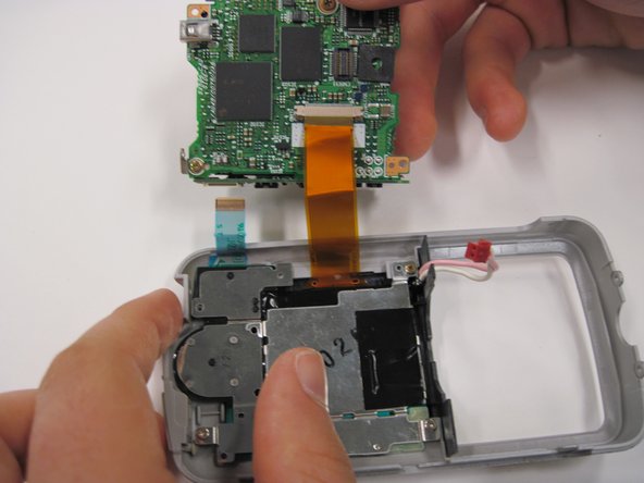
    • Disconnect the blue wire connecting the motherboard to the LED screen.

    • Disconnect the orange wire using a spudger while pushing out horizontally.

    • Disconnect the red capped wire from the motherboard.

    • Lift the motherboard and lens (still connected) out of the back case.

  11. 这个步骤还没有翻译 帮忙翻译一下

    : 步骤 11 中的图像 1,1
    • Lift up on the black covering and remove the orange wire connecting the lens to the motherboard.

终点

richard guenther

于04/19/10注册

183 声望

创作了6篇指南

团队

Cal Poly, Team 30-38, Garner Spring 2010 Cal Poly, Team 30-38, Garner Spring 2010 的会员

CPSU-GARNER-S10S30G38

5 名成员

创作了11篇指南

0条评论

添加评论

浏览统计数据:

过去 24 小时: 2

过去 7 天: 9

过去 30 天: 12

总计 3,008