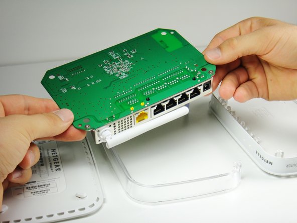
跳转到主内容

Netgear WGR614v9 Capacitor Replacement

你所需要的

  1. Netgear WGR614v9 Capacitor Replacement, Lower Case: 步骤 1 中的图像 1,1
    • Rotate the device so that the bottom is facing up.

  2. Netgear WGR614v9 Capacitor Replacement: 步骤 2 中的图像 1,2 Netgear WGR614v9 Capacitor Replacement: 步骤 2 中的图像 2,2
    • Lift up all four rubber pads on the bottom of the router with the plastic opening tool.

    • Be careful not to pull the rubber pads all the way out when lifting as they are difficult to reinsert.

  3. Netgear WGR614v9 Capacitor Replacement: 步骤 3 中的图像 1,2 Netgear WGR614v9 Capacitor Replacement: 步骤 3 中的图像 2,2
    • Unscrew the four 11.8 mm T-8 torx screws from the bottom of the router.

  4. Netgear WGR614v9 Capacitor Replacement: 步骤 4 中的图像 1,1
    • Lift the bottom casing straight up from the router.

  5. Netgear WGR614v9 Capacitor Replacement, Motherboard: 步骤 5 中的图像 1,1
    • Remove the clear plastic casing by lifting it straight up from the router.

  6. Netgear WGR614v9 Capacitor Replacement: 步骤 6 中的图像 1,2 Netgear WGR614v9 Capacitor Replacement: 步骤 6 中的图像 2,2
    • Separate the motherboard from the top shell by lifting it straight up from the router.

  7. Netgear WGR614v9 Capacitor Replacement, Capacitor: 步骤 7 中的图像 1,2 Netgear WGR614v9 Capacitor Replacement, Capacitor: 步骤 7 中的图像 2,2
    • Rotate the motherboard so that the top is facing up.

    • Set the motherboard on a flat clean surface.

  8. Netgear WGR614v9 Capacitor Replacement: 步骤 8 中的图像 1,2 Netgear WGR614v9 Capacitor Replacement: 步骤 8 中的图像 2,2
    • The capacitor can be found at the location shown.

  9. Netgear WGR614v9 Capacitor Replacement: 步骤 9 中的图像 1,2 Netgear WGR614v9 Capacitor Replacement: 步骤 9 中的图像 2,2
    • Rotate the motherboard so that the bottom is facing up.

    • Locate the two soldered contacts of the capacitor.

  10. Netgear WGR614v9 Capacitor Replacement: 步骤 10 中的图像 1,3 Netgear WGR614v9 Capacitor Replacement: 步骤 10 中的图像 2,3 Netgear WGR614v9 Capacitor Replacement: 步骤 10 中的图像 3,3
    • Rotate the motherboard 180 degrees.

    • Do not refer to the pictures in this step for proper de-soldering and soldering techniques. They are for illustration purposes only.

    • Refer to this link for proper de-soldering and soldering techniques.

    • Pull the capacitor from the other side of the circuit board once the solder is liquified.

    • To replace the capacitor, orient the negative side of the capacitor (indicated by a white stripe and a negative sign) so that it aligns with the shaded white region of the circle indicating the capacitor's position on the motherboard.

结论

To reassemble your device, follow these instructions in reverse order.

另外一个人完成了本指南。

Kyle Moore

于10/03/11注册

95 声望

撰写一个指南

团队

Cal Poly, Team 21-24, Maness Fall 2011 Cal Poly, Team 21-24, Maness Fall 2011 的会员

CPSU-MANESS-F11S21G24

4 名成员

创作了11篇指南

一条评论

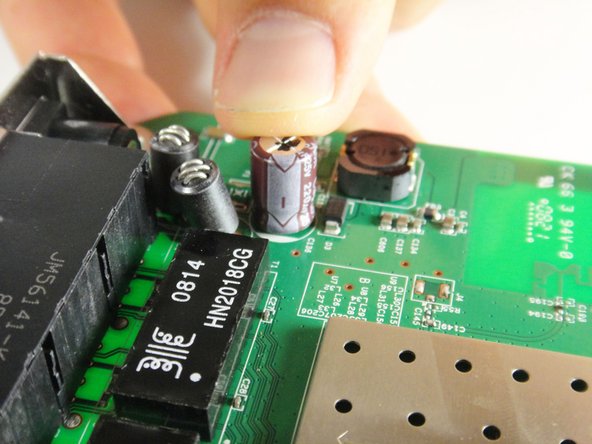
looks like that's a 220microF at 25V right ?

probably better to replace it with a similar 220microF, but with higher voltage rating.

email_etran - 回复

添加评论

浏览统计数据:

过去 24 小时: 0

过去 7 天: 0

过去 30 天: 5

总计 3,199