跳转到主内容

本指南有最近更改,您可查看未经巡查的最新版本

Motorola Defy XT Logic Board Replacement

你所需要的

  1. Motorola Defy XT Logic Board Replacement, Logic Board: 步骤 1 中的图像 1,1
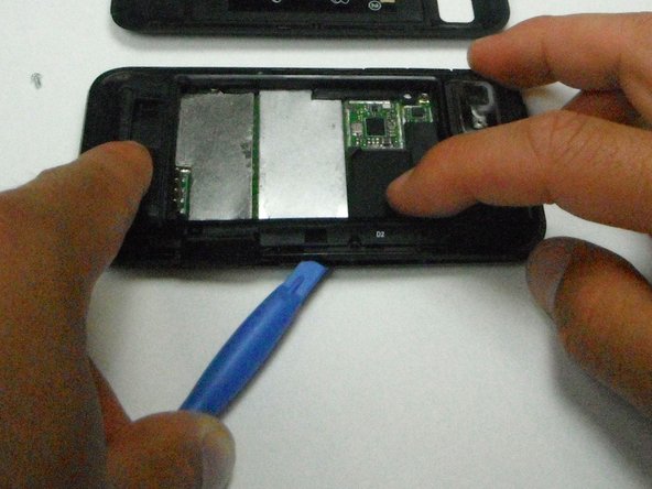
    • Wedge the opening tool in-between the back cover and the body of the phone in the opening denoted by the arrow.

  2. Motorola Defy XT Logic Board Replacement: 步骤 2 中的图像 1,1
    • Once wedged in the opening, slide the opening tool around the side of the phone and remove the back cover, setting it aside.

  3. Motorola Defy XT Logic Board Replacement: 步骤 3 中的图像 1,1
    • Insert the opening tool between the battery and the battery holder and wedge the battery out.

  4. Motorola Defy XT Logic Board Replacement: 步骤 4 中的图像 1,1
    • Open the plastic cover with your finger to expose the SD card.

    • Use the opening tool to grab the edge of the SD card and pull it straight out.

  5. Motorola Defy XT Logic Board Replacement: 步骤 5 中的图像 1,1
    • Remove the six 6mm T4 screws with the T4 torque driver.

  6. Motorola Defy XT Logic Board Replacement: 步骤 6 中的图像 1,1
    • Pop out the volume button with the plastic opening tool.

  7. Motorola Defy XT Logic Board Replacement: 步骤 7 中的图像 1,2 Motorola Defy XT Logic Board Replacement: 步骤 7 中的图像 2,2
    • Wedge the plastic opening tool in-between the plastic layer and the front cover.

    • Do not completely separate the two pieces to avoid damaging the ribbon cable inside.

  8. Motorola Defy XT Logic Board Replacement: 步骤 8 中的图像 1,1
    • Carefully separate the bottom piece from the top plastic piece.

    • Disconnect the ribbon cable connecting the display to the logic board by firmly pulling the cable straight outward.

    • The screen can now be removed.

  9. Motorola Defy XT Logic Board Replacement: 步骤 9 中的图像 1,1
    • Separate the logic board and the display cover from the back cover and orient the logic board so the camera faces toward you.

    • Disconnect the back cover by wedging the plastic opening tool in between the motherboard and the connector and prying outward.

  10. Motorola Defy XT Logic Board Replacement: 步骤 10 中的图像 1,1
    • Flip the logic board and display cover over so the camera faces away from you.

    • Bend the two halves of the device away from you to pry the final ribbon connector off the logic board.

    • The ribbon connector is bonded to the logic board with adhesive, simply pull it to break the glue bond.

结论

To reassemble your device, follow these instructions in reverse order.

2等其他人完成本指南。

No Name

于04/21/13注册

25 声望

撰写一个指南

0条评论

添加评论

浏览统计数据:

过去 24 小时: 0

过去 7 天: 0

过去 30 天: 0

总计 1,305