跳转到主内容

当前版本的文档还未经巡查,您可以查看最新的已查核版本

仅作为前提条件
本指南仅用作其他指南的先决条件。不能单独食用。

你所需要的

  1. , 电池盖: 步骤 1 中的图像 1,1
    • 笔记本盒盖,然后笔记本底部朝上放置

    • 按下位于底盖右侧的电池盖门闩,当电池盖被提起到可以拿起的程度时就可以放下门闩至与底盖齐平。

  2. : 步骤 2 中的图像 1,1
    • 这时如果正常的话握着边缘就能很轻松地拿出盖子

  3. 这个步骤还没有翻译 帮忙翻译一下

    : 步骤 3 中的图像 1,1
    • Be sure the access door release latch is vertical before proceeding.

    • Grab the white plastic tab and pull the battery up and out of the Unibody.

  4. 这个步骤还没有翻译 帮忙翻译一下

    : 步骤 4 中的图像 1,1
    • Remove the following eight screws securing the lower case to the chassis:

    • One 3 mm Phillips screw.

    • Three 13.5 mm Phillips screws.

    • Four 3.5 mm Phillips screws.

  5. 这个步骤还没有翻译 帮忙翻译一下

    : 步骤 5 中的图像 1,1
    • Using both hands, lift and remove the lower case off the upper case.

  6. 这个步骤还没有翻译 帮忙翻译一下

    : 步骤 6 中的图像 1,1
    • Disconnect the camera cable by pulling the male end straight away from its socket.

    • Be careful not to pull up on the cable as you remove it from the socket.

  7. 这个步骤还没有翻译 帮忙翻译一下

    : 步骤 7 中的图像 1,2 : 步骤 7 中的图像 2,2
    • De-route the camera data cable from the channel in the optical drive.

  8. 这个步骤还没有翻译 帮忙翻译一下

    : 步骤 8 中的图像 1,2 : 步骤 8 中的图像 2,2
    • Remove the following screws securing the camera data cable and right speaker to the upper case:

    • One 9.9 mm partially threaded Phillips screw

    • One 9.6 mm threaded Phillips screw

    • One 4 mm Phillips screw

    • Slide the camera cable bracket out from under the subwoofer and remove it from the computer.

    • The iSight cable has an eyelet through which passes the left-most screw in these pictures.

  9. 这个步骤还没有翻译 帮忙翻译一下

    : 步骤 9 中的图像 1,2 : 步骤 9 中的图像 2,2
    • Grab the plastic pull tab secured to the display data cable lock and rotate it toward the DC-in side of the computer.

    • Pull the display data cable connector straight away from its socket.

    • Make sure to pull the connector straight away and not straight up from its socket.

  10. 这个步骤还没有翻译 帮忙翻译一下

    : 步骤 10 中的图像 1,2 : 步骤 10 中的图像 2,2
    • Remove the following two screws from the display data cable bracket:

    • One 7 mm Phillips screw.

    • One 5 mm Phillips screw.

    • Lift the display data cable bracket out of the upper case.

  11. 这个步骤还没有翻译 帮忙翻译一下

    : 步骤 11 中的图像 1,1
    • Remove the two outer 6 mm Torx screws securing each side of the display to the upper case (4 screws total).

  12. 这个步骤还没有翻译 帮忙翻译一下

    : 步骤 12 中的图像 1,1
    • Open your MacBook so the display is perpendicular to the upper case.

    • Place your opened MacBook on a table as pictured.

    • While holding the display and upper case together with your left hand, remove the 6 mm Torx screw from the lower display bracket.

  13. 这个步骤还没有翻译 帮忙翻译一下

    : 步骤 13 中的图像 1,1
    • Be sure to hold the display and upper case together with your left hand. Failure to do so may cause the freed display/upper case to fall, potentially damaging each component.

    • Remove the last remaining 6 mm Torx screw securing the display to the upper case.

  14. 这个步骤还没有翻译 帮忙翻译一下

    : 步骤 14 中的图像 1,3 : 步骤 14 中的图像 2,3 : 步骤 14 中的图像 3,3
    • Grab the upper case with your right hand and rotate it slightly toward the top of the display so the upper display bracket clears the edge of the upper case.

    • Rotate the display slightly away from the upper case.

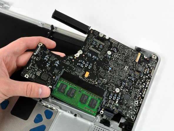
    • Lift the display away from the upper case, minding any brackets or cables that may get caught.

  15. 这个步骤还没有翻译 帮忙翻译一下

    : 步骤 15 中的图像 1,2 : 步骤 15 中的图像 2,2
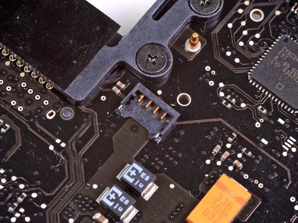
    • Some 2.0 GHz A1278 MacBook Unibody logic boards do not have the necessary socket installed to accept the keyboard backlight ribbon cable attached to the upper case. The first and second pictures show logic boards with and without the socket installed, respectively. If your logic board does not have the backlight ribbon cable socket installed, the keyboard will work but the keys will not light up.

    • If your logic board does not have the socket installed to accept the keyboard backlight ribbon cable and you are installing a backlit upper case, simply tuck the keyboard backlight ribbon cable out of the way when you reinstall the logic board into the upper case.

  16. 这个步骤还没有翻译 帮忙翻译一下

    : 步骤 16 中的图像 1,1
    • Remove the single Phillips screw securing the hard drive bracket to the chassis.

    • This screw is captive to the hard drive bracket.

  17. 这个步骤还没有翻译 帮忙翻译一下

    : 步骤 17 中的图像 1,1
    • Lift the hard drive by its pull tab enough to grab and remove the retaining bracket.

    • Lift the hard drive out of the chassis, minding the cable attaching it to the computer.

  18. 这个步骤还没有翻译 帮忙翻译一下

    : 步骤 18 中的图像 1,1
    • Remove the hard drive from its cable by pulling the cable connector straight away from the drive.

  19. 这个步骤还没有翻译 帮忙翻译一下

    : 步骤 19 中的图像 1,1
    • Remove the four 10.3 mm Phillips screws securing the mid wall to the upper case.

  20. 这个步骤还没有翻译 帮忙翻译一下

    : 步骤 20 中的图像 1,1
    • Lift the mid wall out of the upper case.

  21. 这个步骤还没有翻译 帮忙翻译一下

    : 步骤 21 中的图像 1,1
    • Remove the following three screws securing the fan to the upper case:

    • Two 5 mm Phillips screws.

    • One 7 mm Phillips screw.

  22. 这个步骤还没有翻译 帮忙翻译一下

    : 步骤 22 中的图像 1,3 : 步骤 22 中的图像 2,3 : 步骤 22 中的图像 3,3
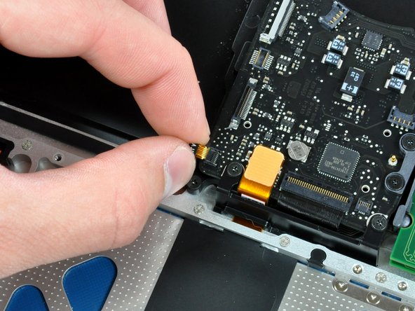
    • Use a spudger to pry the fan connector straight up and out of its socket on the logic board.

    • It is useful to twist the spudger axially from beneath the fan cable wires to release the connector.

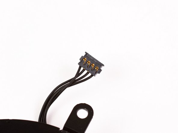
    • The fan socket and the fan connector can be seen in the second and third pictures. Be careful not to break the plastic fan socket off the logic board as you use your spudger to lift the fan connector straight up and out of its socket. The layout of the logic board shown in the second picture may look slightly different than your machine but the fan socket is the same.

  23. 这个步骤还没有翻译 帮忙翻译一下

    : 步骤 23 中的图像 1,1
    • Lift the fan out of the upper case.

  24. 这个步骤还没有翻译 帮忙翻译一下

    : 步骤 24 中的图像 1,1
    • Using the flat end of a spudger, pry the subwoofer connector straight up off the logic board.

  25. 这个步骤还没有翻译 帮忙翻译一下

    : 步骤 25 中的图像 1,1
    • Remove the single Phillips screw securing the subwoofer to the upper case.

  26. 这个步骤还没有翻译 帮忙翻译一下

    : 步骤 26 中的图像 1,1
    • The subwoofer is still connected to the right speaker, so don't completely remove it just yet.

    • Lift the subwoofer off the optical drive, and set it above the computer.

  27. 这个步骤还没有翻译 帮忙翻译一下

    : 步骤 27 中的图像 1,1
    • Use a spudger to pry the optical drive connector straight up off the logic board.

  28. 这个步骤还没有翻译 帮忙翻译一下

    : 步骤 28 中的图像 1,1
    • Use the flat end of a spudger to pry the hard drive cable connector straight up off the logic board.

  29. 这个步骤还没有翻译 帮忙翻译一下

    : 步骤 29 中的图像 1,2 : 步骤 29 中的图像 2,2
    • Remove the three 2.5 mm Phillips screws securing the optical drive to the upper case.

  30. 这个步骤还没有翻译 帮忙翻译一下

    : 步骤 30 中的图像 1,1
    • Lift the optical drive from its right edge and pull it out of the computer.

  31. 这个步骤还没有翻译 帮忙翻译一下

    : 步骤 31 中的图像 1,2 : 步骤 31 中的图像 2,2
    • Peel the hard drive cable from the adhesive securing it to the upper case, and maneuver the plastic retaining block out of the upper case.

    • The hard drive cable and the plastic retaining block are attached together.

  32. 这个步骤还没有翻译 帮忙翻译一下

    : 步骤 32 中的图像 1,3 : 步骤 32 中的图像 2,3 : 步骤 32 中的图像 3,3
    • Peel back the small piece of black tape covering the right speaker cable.

    • Use the tip of a spudger to pry the right speaker up off the adhesive securing it to the upper case.

    • Lift the subwoofer and right speaker assembly out of the upper case.

  33. 这个步骤还没有翻译 帮忙翻译一下

    : 步骤 33 中的图像 1,2 : 步骤 33 中的图像 2,2
    • Use the tip of a spudger to flip up the locking lever to release the IR sensor ribbon cable from its socket.

    • Pull the IR sensor ribbon cable straight away from the logic board.

  34. 这个步骤还没有翻译 帮忙翻译一下

    : 步骤 34 中的图像 1,1
    • Use the flat end of a spudger to pry the trackpad connector straight up off the logic board.

  35. 这个步骤还没有翻译 帮忙翻译一下

    : 步骤 35 中的图像 1,2 : 步骤 35 中的图像 2,2
    • Using the tip of a spudger, flip up the keyboard ribbon cable retaining flap.

    • Pull the keyboard ribbon cable straight out of its socket.

  36. 这个步骤还没有翻译 帮忙翻译一下

    : 步骤 36 中的图像 1,2 : 步骤 36 中的图像 2,2
    • Remove the two 5 mm Phillips screws securing the keyboard flex bracket to the upper case.

    • Lift the keyboard flex bracket out of the upper case.

  37. 这个步骤还没有翻译 帮忙翻译一下

    : 步骤 37 中的图像 1,2 : 步骤 37 中的图像 2,2
    • Remove the single Phillips screw securing the battery cable cover to the upper case.

    • Remove the battery cable cover from the upper case.

  38. 这个步骤还没有翻译 帮忙翻译一下

    : 步骤 38 中的图像 1,1
    • Use a spudger to pry the battery level indicator cable connector straight up off the logic board.

  39. 这个步骤还没有翻译 帮忙翻译一下

    : 步骤 39 中的图像 1,1
    • Disconnect the battery cable connector by pulling it straight away from the logic board.

    • If you cannot grasp the cable with your fingers, a spudger and tweezers may be helpful for removal.

  40. 这个步骤还没有翻译 帮忙翻译一下

    : 步骤 40 中的图像 1,2 : 步骤 40 中的图像 2,2
    • Remove the two 4mm Phillips screws securing the bottom case clip to the upper case.

    • Lift the bottom case clip out of the upper case.

  41. 这个步骤还没有翻译 帮忙翻译一下

    : 步骤 41 中的图像 1,1
    • Use the tip of a spudger to release the microphone from the upper case.

  42. 这个步骤还没有翻译 帮忙翻译一下

    : 步骤 42 中的图像 1,2 : 步骤 42 中的图像 2,2
    • Remove the following five screws securing the logic board to the upper case:

    • Four 3 mm Phillips screws.

    • One 3.5 mm Phillips screw.

    • Remove the two 7 mm Phillips screws securing the DC-in board to the upper case.

    • Lift the logic board from its left edge and pull it out of the upper case.

  43. 这个步骤还没有翻译 帮忙翻译一下

    : 步骤 43 中的图像 1,2 : 步骤 43 中的图像 2,2
    • If you are buying a new upper case from us, the next two steps are not necessary. Your upper case will come with these parts preinstalled.

    • Remove the following screws securing the battery connector cover to the upper case:

    • One 2.5 mm Phillips screw.

    • Two 1.5 mm Phillips screws.

    • Lift the battery connector cover out of the upper case.

  44. 这个步骤还没有翻译 帮忙翻译一下

    : 步骤 44 中的图像 1,1
    • De-route the battery connector cable through the gap in the upper case and remove it from the computer.

    • If you are installing an Upper Case that is missing the black bracket in the middle then transfer it from the old case to the replacement.

终点

26等其他人完成本指南。

一条评论

Having difficulty putting that keyboard ribbon cable back in?

MacBook unibody keyboard ribbon cable won't go in

Put some scotch tape on it and pull up and in.

Peter LaComb - 回复

添加评论

浏览统计数据:

过去 24 小时: 0

过去 7 天: 0

过去 30 天: 1

总计 80,757