Whenever working near the logic board, it is always wise to first disconnect the battery to avoid short circuits.
If present, grab the plastic tab attached to the battery connector and pull it toward the front edge of the device. For Late-2011 models the battery connector will not have a tab and is simply a plug that inserts straight down into the motherboard--to remove pry the plug straight up.
If the plastic tab is missing, use a spudger to pry the connector up from its socket.
Pull the tab parallel to the face of the logic board.
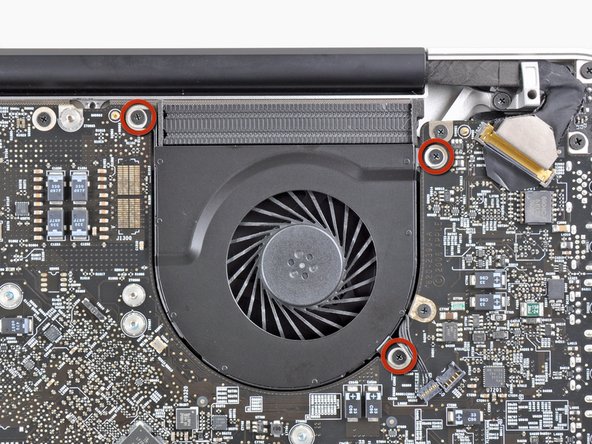
Use the flat end of a spudger to lift the right fan connector out of its socket on the logic board.
It is useful to twist the spudger axially from beneath the fan cable wires to release the connector.
The fan socket and the fan connector can be seen in the second and third pictures. Be careful not to break the plastic fan socket off the logic board as you use your spudger to lift the fan connector straight up and out of its socket. The layout of the logic board shown in the second picture may look slightly different than your machine but the fan socket is the same.
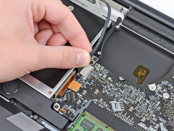
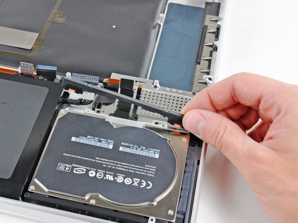
Pull the camera cable toward the optical drive opening to disconnect it from the logic board.
The camera cable socket is very fragile. Do not apply any upward force to this socket, as it may break off the logic board. Pull the camera cable parallel to the face of the logic board.
Use your fingernail to flip up the retaining flap on the keyboard ribbon cable socket.
Be sure you are prying up on the retaining flap, not the socket itself.
Pull the keyboard ribbon cable out of its socket.
For reassembly, it can be helpful to put a small piece of tape on the keyboard ribbon cable (being careful not to stick any to the contacts), to create a small handle. Align the cable with the socket and gently pull with the tape to fully seat it.
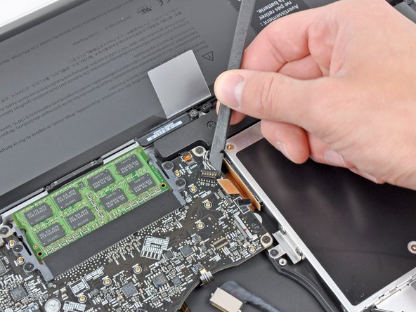
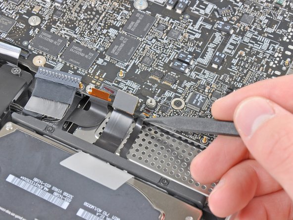
Lift the black plastic flap attached to the display data cable retainer and rotate it toward the DC-In side of the MacBook.
Pull the display data cable out of its socket.
The display data cable socket is very fragile. Do not lift the connector upward as you disconnect it, as the socket may break off the logic board. Pull the cable parallel to the face of the logic board.
Handle the logic board assembly by its edges only.
Lift the logic board assembly from the side nearest the optical drive and lift it away from the upper case.
Note that you'll be removing the logic board and DC-in board together.
Carefully pull the ports and DC-In board away from the side of the upper case and remove the logic board assembly, minding any cables that may get caught.