Whenever working near the logic board, it is always wise to first disconnect the battery to avoid short circuits.
If present, grab the plastic tab attached to the battery connector and pull it toward the front edge of the device. For Late-2011 models the battery connector will not have a tab and is simply a plug that inserts straight down into the motherboard--to remove pry the plug straight up.
If the plastic tab is missing, use a spudger to pry the connector up from its socket.
Pull the tab parallel to the face of the logic board.
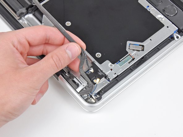
Before disconnecting the camera cable, a small plastic retainer stuck to the logic board must first be moved out of the way. In late-2011 models you can skip this step because there is not a plastic retainer on the camera cable connector.
Use the tip of a spudger to push the small plastic cable retainer away from the camera cable socket for enough clearance to remove the camera cable.
Pull the camera cable toward the optical drive opening to disconnect it from the logic board.
The camera cable socket is very fragile. Do not apply any upward force to this socket, as it may break off the logic board. Pull the camera cable parallel to the face of the logic board.
Use the flat end of a spudger to peel the thin plastic cover off the top and sides of the Bluetooth board housing. For late-2011 models check out the other picture because the connector location is in a totally different location.
Lift the black plastic flap attached to the display data cable retainer and rotate it toward the DC-In side of the MacBook.
Pull the display data cable out of its socket.
The display data cable socket is very fragile. Do not lift the connector upward as you disconnect it, as the socket may break off the logic board. Pull the cable parallel to the face of the logic board.
Be sure to hold the display and upper case together with your left hand. Failure to do so may cause the freed display/upper case to fall, potentially damaging each component.
Remove the last remaining T6 Torx screw securing the display to the upper case.
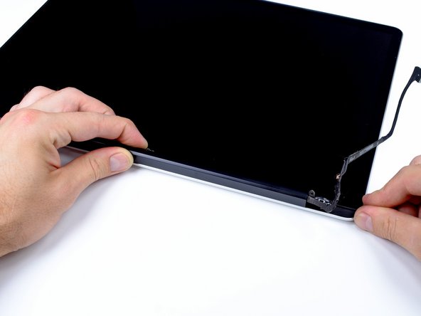
Grab the upper case with your right hand and rotate it slightly toward the top of the display so the upper display bracket clears the edge of the upper case.
Rotate the display slightly away from the upper case.
Lift the display up and away from the upper case, minding any brackets or cables that may get caught.
During reassembly, fit the display into place and install the display bracket Torx screws, then close the lid and lay the laptop upside-down to check the alignment of the screen to the body. If necessary, loosen the screws and realign the display before tightening.
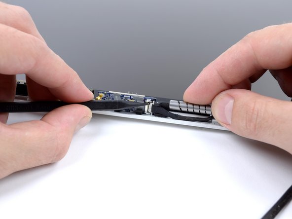
Move the AirPort board bracket towards the bottom of the display case with the tip of a spudger so that it does not block the AirPort board cable.
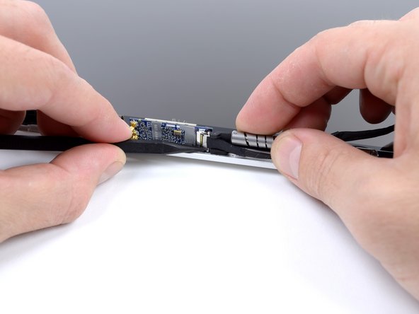
Use the tip of a spudger to disconnect the AirPort board cable by rocking it back and forth until it is free.
The AirPort board connection cable can be inserted both ways. The two sides of the connector look slightly different. However, inserting it upside down will cause a short circuit upon power on and damage the logic board and/or Airport board, so be careful to note the correct orientation.
Just a note for anyone looking at this guide with a MacBook Pro 17" mid 2010 model (2.6GHz) - this is the wrong guide for your laptop! Search for the MacBook Pro 15" mid 2010 Airport board replacement guide instead. The card is located on top of the optical drive rather than in the bezel - something i found out the hard way when following this ;)