跳转到主内容

当前版本的文档还未经巡查,您可以查看最新的已查核版本

你所需要的

  1. , 底壳: 步骤 1 中的图像 1,1
    • 拆除以下十颗固定在机壳上的螺丝

    • 三颗13.5mm(14.1 mm) 菲利普斯十字螺丝 。

    • 七颗3 mm 菲利普斯十字螺丝。

    • 卸下这些螺丝时,请注意它们如何以很小的角度伸出。必须以相同的方式重新安装它们。

  2. : 步骤 2 中的图像 1,1
    • 使用双手在后壳接近风扇处提起固定后壳的两个卡扣。

    • 将后壳放置在一边。

  3. , 电池排线: 步骤 3 中的图像 1,2 , 电池排线: 步骤 3 中的图像 2,2
    • 对于某些维修(例如硬盘),不需要断开电池连接器,但断开连接器可防止主板上电子设备的意外短路。 如果不断开电池连接器,请小心,因为主板的部件可能会通电造成短路或其他伤害。

    • 使用撬棒的边缘从逻辑板上的插座向上撬开电池连接器。

    • 在连接器的两个短边上分别向上撬起插座是十分有效的手段。

  4. : 步骤 4 中的图像 1,1
    • 将电池电缆稍微掰离主板上的插座,以免在进行其他工作时插头与插座意外连接。

  5. 这个步骤还没有翻译 帮忙翻译一下

    : 步骤 5 中的图像 1,1
    • Remove the following three screws securing the left fan to the logic board:

    • Two 3.5 mm T6 Torx screws.

    • One 4.2 mm T6 Torx screw.

  6. 这个步骤还没有翻译 帮忙翻译一下

    : 步骤 6 中的图像 1,3 : 步骤 6 中的图像 2,3 : 步骤 6 中的图像 3,3
    • Use the flat end of a spudger to disconnect the left fan connector from the logic board.

    • It is useful to twist the spudger axially from beneath the fan cable wires to release the connector.

    • The fan socket and the fan connector can be seen in the second and third pictures. Be careful not to break the plastic fan socket off the logic board as you use your spudger to lift the fan connector straight up and out of its socket.

    • The layout of the logic board shown in the second picture may look slightly different than your machine but the fan socket is the same.

  7. 这个步骤还没有翻译 帮忙翻译一下

    : 步骤 7 中的图像 1,1
    • Lift the left fan out of the upper case.

  8. , 逻辑板: 步骤 8 中的图像 1,1
    • 使用撬棒扁平的一端从逻辑板上的插座中撬起右风扇的插头。

    • 小提示:在风扇线缆下方扭动撬棒来断开插头。

  9. : 步骤 9 中的图像 1,2 : 步骤 9 中的图像 2,2
    • 移除将右侧风扇和逻辑板固定的三颗3.4mm(3.1mm)T6 梅花螺丝。

    • 从逻辑板上的开口提出风扇。

  10. : 步骤 10 中的图像 1,1
    • 从逻辑板的插座上拉出摄像头线缆。

    • 断开连接时,请勿向上拉动相机线缆。 这样可能损坏逻辑板和线缆本身。 将电缆从逻辑板平行的方向拉出。

  11. : 步骤 11 中的图像 1,1
    • 使用撬棒扁平的一端来撬开逻辑板插座上的AirPort/蓝牙排线的插头。

  12. : 步骤 12 中的图像 1,1
    • 使用撬棒扁平一端来撬起逻辑板插座上的光驱排线的插头。

  13. : 步骤 13 中的图像 1,1
    • 从逻辑板上的插头下撬起硬盘红外传感器线缆。

  14. : 步骤 14 中的图像 1,1
    • 使用撬棒扁平的一端从逻辑板的插座上撬起低音扬声器/右扬声器线缆的插头。

    • 在线缆下方撬起。

  15. : 步骤 15 中的图像 1,2 : 步骤 15 中的图像 2,2
    • 移除将键盘/触摸板固定到逻辑板上的两颗1.5mm(1.2mm)十字螺丝。

    • 从逻辑板上提起盖子,放置到一边。

  16. : 步骤 16 中的图像 1,1
    • 从逻辑板的插座上撬起触摸板排线连接插头。

  17. : 步骤 17 中的图像 1,2 : 步骤 17 中的图像 2,2
    • 使用您的指甲来撬动键盘排线上的ZIF插座的滑杆。

    • 确保您撬动的是滑杆,而不是插座本身。

    • 使用撬棒的尖端将键盘排线从插座中拉出。

  18. : 步骤 18 中的图像 1,1
    • 使用撬棒扁平的一端来从逻辑板插座中提起电量显示插头。

  19. : 步骤 19 中的图像 1,2 : 步骤 19 中的图像 2,2
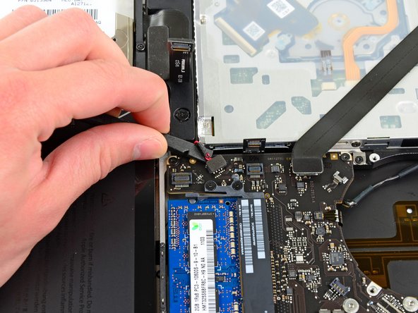
    • 抓住将显示数据排线锁固定的塑料拉手,并将其旋转到电脑交流电插口方向。

    • 将显示数据电缆直接从逻辑板上的插座拉出

    • 不要抬起显示数据线,因为它的插座非常脆弱。 将电缆平行于逻辑板的表面拉出。

  20. : 步骤 20 中的图像 1,2 : 步骤 20 中的图像 2,2
    • 使用撬棒的尖端来从ZIF插座中撬起键盘背光排线。

    • 确保您撬动的是滑杆而不是插座本身。

    • 从插座中拉出背光排线。

  21. : 步骤 21 中的图像 1,1
    • 移除下列螺丝

    • 逻辑板上的7颗3.4mm(3.1mm)T6 梅花螺丝。

    • 2颗交流电源板上的8mm T6 梅花螺丝。

  22. : 步骤 22 中的图像 1,3 : 步骤 22 中的图像 2,3 : 步骤 22 中的图像 3,3
    • 小心地从左侧提起逻辑电路板组件,并将其从外壳中移出,清理光盘驱动器电缆和可能在拆卸过程中被卡住的I / O端口。

    • 如有必要,请使用撬棒扁平的一端将麦克风与上壳分开。

    • 将逻辑板的I / O端口侧拉离上盖的一侧,然后卸下逻辑板组合件。

  23. 这个步骤还没有翻译 帮忙翻译一下

    : 步骤 23 中的图像 1,1
    • Disconnect the DC-In board by pulling its cable toward the heat sink.

    • Pull the cable parallel to the face of the logic board.

终点

41等其他人完成本指南。

团队

iFixit iFixit 的会员

Staff

135 名成员

创作了16,731篇指南

6条评论

Dont want to double post so please refer to the guide for the display to see my issue, but folwed teh guide to the T. The only anomaly i found ater reseting everything again is darkish tint ont he display cable, the rest of hte story is on my post on guides for displa. any help guys will be greatly appreciated. I'll defintelyl guys you guys business from here on how, And yes i know i work or apple but his machine ha my bitcoins.and pgp keys. and i still love her.

mark Andrews - 回复

Good tutorial. New DC board installed and Macbook now charges without getting hot at all.

bill borez - 回复

Thank you, followed this and fixed my macbook. My only difficulty was with removing the display cable until I realized that there’s a hinged wire clip in front of the socket that must be lifted up and over the socket before removal. Very helpful guide..

robertlucier - 回复

Thanks for this tutorial ,New DC Board installed but my macbook a1286 charged 60% and he doesn’t work.

how can i see to check what going wrong i know this channel ,https://www.youtube.com/channel/UCl2mFZo...,

But i dont know if should check data sense line or which step and material i need (multimeter)

thanks for any reply

sorry for my english im “French” :)

soufiane - 回复

Excellent tutorial. Whole project start to finish was successful in under an hour. Extreme attention to screw size/lengths was great and the order was also perfect.

Ben Patch - 回复

添加评论

浏览统计数据:

过去 24 小时: 7

过去 7 天: 12

过去 30 天: 65

总计 18,648