跳转到主内容

当前版本的文档还未经巡查,您可以查看最新的已查核版本

你所需要的

  1. , 底壳: 步骤 1 中的图像 1,1
    • 拆除以下十颗固定在机壳上的螺丝

    • 三颗13.5mm(14.1 mm) 菲利普斯十字螺丝 。

    • 七颗3 mm 菲利普斯十字螺丝。

    • 卸下这些螺丝时,请注意它们如何以很小的角度伸出。必须以相同的方式重新安装它们。

  2. : 步骤 2 中的图像 1,1
    • 使用双手在后壳接近风扇处提起固定后壳的两个卡扣。

    • 将后壳放置在一边。

  3. , 电池排线: 步骤 3 中的图像 1,2 , 电池排线: 步骤 3 中的图像 2,2
    • 对于某些维修(例如硬盘),不需要断开电池连接器,但断开连接器可防止主板上电子设备的意外短路。 如果不断开电池连接器,请小心,因为主板的部件可能会通电造成短路或其他伤害。

    • 使用撬棒的边缘从逻辑板上的插座向上撬开电池连接器。

    • 在连接器的两个短边上分别向上撬起插座是十分有效的手段。

  4. : 步骤 4 中的图像 1,1
    • 将电池电缆稍微掰离主板上的插座,以免在进行其他工作时插头与插座意外连接。

  5. , 电池: 步骤 5 中的图像 1,1
    • 卸下将电池固定到上壳上的两个7.4 mm三点螺丝。

  6. : 步骤 6 中的图像 1,1
    • 小心的将贴在电池和光驱上的电池警告贴纸撕开。 然后移除另外一颗三点螺丝。

    • 移除最后一颗将电池固定在上壳的 Y0 7.4mm三点螺丝。

    • 切勿将贴纸从电池上完全撕下。

  7. : 步骤 7 中的图像 1,1
    • 使用电池顶部的塑料拉手拉出电池。

    • 如果你在安装新电池,你应该在安装完成后进行校准

    • 把电池充满,然后至少继续充电两个小时。之后,像往常一样使用它,消耗电量。当你看到低电量警告时,保存好你的工作,然后让笔记本开着,直到它因为低电量而入睡。再等待至少五个小时,之后再把你的笔记本充满到100%

    • 如果在安装新电池后你发现了一些异常状况或麻烦,你可能需要重置你的Macbook的设备管理器

  8. 这个步骤还没有翻译 帮忙翻译一下

    : 步骤 8 中的图像 1,1
    • Remove the following three screws securing the left fan to the logic board:

    • Two 3.5 mm T6 Torx screws.

    • One 4.2 mm T6 Torx screw.

  9. 这个步骤还没有翻译 帮忙翻译一下

    : 步骤 9 中的图像 1,3 : 步骤 9 中的图像 2,3 : 步骤 9 中的图像 3,3
    • Use the flat end of a spudger to disconnect the left fan connector from the logic board.

    • It is useful to twist the spudger axially from beneath the fan cable wires to release the connector.

    • The fan socket and the fan connector can be seen in the second and third pictures. Be careful not to break the plastic fan socket off the logic board as you use your spudger to lift the fan connector straight up and out of its socket.

    • The layout of the logic board shown in the second picture may look slightly different than your machine but the fan socket is the same.

  10. 这个步骤还没有翻译 帮忙翻译一下

    : 步骤 10 中的图像 1,1
    • Lift the left fan out of the upper case.

  11. , 逻辑板: 步骤 11 中的图像 1,1
    • 使用撬棒扁平的一端从逻辑板上的插座中撬起右风扇的插头。

    • 小提示:在风扇线缆下方扭动撬棒来断开插头。

  12. : 步骤 12 中的图像 1,2 : 步骤 12 中的图像 2,2
    • 移除将右侧风扇和逻辑板固定的三颗3.4mm(3.1mm)T6 梅花螺丝。

    • 从逻辑板上的开口提出风扇。

  13. : 步骤 13 中的图像 1,1
    • 从逻辑板的插座上拉出摄像头线缆。

    • 断开连接时,请勿向上拉动相机线缆。 这样可能损坏逻辑板和线缆本身。 将电缆从逻辑板平行的方向拉出。

  14. : 步骤 14 中的图像 1,1
    • 使用撬棒扁平的一端来撬开逻辑板插座上的AirPort/蓝牙排线的插头。

  15. : 步骤 15 中的图像 1,1
    • 使用撬棒扁平一端来撬起逻辑板插座上的光驱排线的插头。

  16. : 步骤 16 中的图像 1,1
    • 从逻辑板上的插头下撬起硬盘红外传感器线缆。

  17. : 步骤 17 中的图像 1,1
    • 使用撬棒扁平的一端从逻辑板的插座上撬起低音扬声器/右扬声器线缆的插头。

    • 在线缆下方撬起。

  18. : 步骤 18 中的图像 1,2 : 步骤 18 中的图像 2,2
    • 移除将键盘/触摸板固定到逻辑板上的两颗1.5mm(1.2mm)十字螺丝。

    • 从逻辑板上提起盖子,放置到一边。

  19. : 步骤 19 中的图像 1,1
    • 从逻辑板的插座上撬起触摸板排线连接插头。

  20. : 步骤 20 中的图像 1,2 : 步骤 20 中的图像 2,2
    • 使用您的指甲来撬动键盘排线上的ZIF插座的滑杆。

    • 确保您撬动的是滑杆,而不是插座本身。

    • 使用撬棒的尖端将键盘排线从插座中拉出。

  21. : 步骤 21 中的图像 1,1
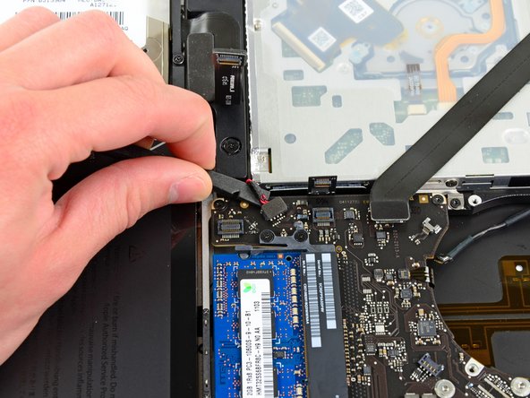
    • 使用撬棒扁平的一端来从逻辑板插座中提起电量显示插头。

  22. : 步骤 22 中的图像 1,2 : 步骤 22 中的图像 2,2
    • 抓住将显示数据排线锁固定的塑料拉手,并将其旋转到电脑交流电插口方向。

    • 将显示数据电缆直接从逻辑板上的插座拉出

    • 不要抬起显示数据线,因为它的插座非常脆弱。 将电缆平行于逻辑板的表面拉出。

  23. : 步骤 23 中的图像 1,2 : 步骤 23 中的图像 2,2
    • 使用撬棒的尖端来从ZIF插座中撬起键盘背光排线。

    • 确保您撬动的是滑杆而不是插座本身。

    • 从插座中拉出背光排线。

  24. : 步骤 24 中的图像 1,1
    • 移除下列螺丝

    • 逻辑板上的7颗3.4mm(3.1mm)T6 梅花螺丝。

    • 2颗交流电源板上的8mm T6 梅花螺丝。

  25. : 步骤 25 中的图像 1,3 : 步骤 25 中的图像 2,3 : 步骤 25 中的图像 3,3
    • 小心地从左侧提起逻辑电路板组件,并将其从外壳中移出,清理光盘驱动器电缆和可能在拆卸过程中被卡住的I / O端口。

    • 如有必要,请使用撬棒扁平的一端将麦克风与上壳分开。

    • 将逻辑板的I / O端口侧拉离上盖的一侧,然后卸下逻辑板组合件。

  26. , 散热器: 步骤 26 中的图像 1,1
    • 将逻辑板放在柔软的平坦表面上,散热片朝上。

    • 拆下将散热器固定到逻辑板上的六颗1号十字螺丝。

    • 跟踪每个螺丝下方的小弹簧。

  27. : 步骤 27 中的图像 1,1
    • 从逻辑板上取下散热片。

    • 拆下所有六颗螺丝后,如果散热看起来卡在逻辑板上,则可能借助使用撬棒分离两个部件。

    • 如果您需要将散热安装到逻辑板上,我们有一个导热板可以更换热敏电阻。

  28. , 逻辑板: 步骤 28 中的图像 1,1
    • 如果有必要,将麦克风从左侧扬声器外壳的凹槽中提起。

  29. : 步骤 29 中的图像 1,1
    • 将固定左侧扬声器的两个5毫米十字螺丝从逻辑板上拧出来。

  30. : 步骤 30 中的图像 1,1
    • 如果存在,请取下覆盖左侧扬声器的黑色小带条。

    • 小心地将左扬声器线向上拉,将左扬声器从逻辑板上的插座中取出。

  31. : 步骤 31 中的图像 1,1
    • 小心地将麦克风电线向上拉,将麦克风从逻辑板上的插座中取出。

  32. : 步骤 32 中的图像 1,1
    • 将DC-In板电线拉向散热器,以将DC-In板与逻辑板上的插座断开。

    • 将电线平行于逻辑板的表面拉出。

  33. : 步骤 33 中的图像 1,2 : 步骤 33 中的图像 2,2
    • 通过同时将每个标签从RAM中打开RAM芯片两侧的插槽。

    • 这些标签将芯片锁定到位,打开它们将导致芯片“弹出”。

    • RAM芯片弹出后,将其从插槽中直接拉出。

    • 如果安装了第二个RAM芯片,则重复此过程。

    • 逻辑板仍然在。

    • 如果您需要将散热安装到逻辑板上,我们有一个导热板可以更换热敏电阻。

终点

62等其他人完成本指南。

团队

iFixit iFixit 的会员

Staff

135 名成员

创作了16,816篇指南

9条评论

For step 5 and 6, maybe a reference could be added to a screwdriver for the Tri-wing screws - this seems quite difficult to find (and in the right size...).

Else I agree to what was said before - an excellent guide!

Jan Hedlund - 回复

ifixit does it again. Thanks so much for making this resource available. Macbooks are so expensive and its great to be able to fix them and keep em going.

lkaneshiro - 回复

where's a good place to find decent condition logic boards My son was in Afghanistan and there for a long fricking time. While he was gone I had gotten him a MACBOOK Pro 15 loaded anyway It was made in mid-2012 He didn''t even get to use until he was home in 2015 and I hadn't used it. after a couple months he got the froze gray screen with apple logo. Called apple did every single thing possible. Finally they said bring into service center. I did they said would have to go in for repair and wasn't a retina display so I would have to pay . They couldn't tell me exact cost but esitmated at oveer $500.So I googled and I guess it's the graphics which you'd need to replace LB what do you think? Is there another fix? I can do work on windows stuff all the time just never Mac this will be my first. So need good sources if you can help I'd appreciate it. Russ

Russ Eastburn (ESP1000) - 回复

I have what appears to be a slightly different mainboard from all 15” unibody models. Could anybody help me identify my mainboard and maybe point me to the fuse for the LCD display back light ?

https://pasteboard.co/I729rA5.jpg

https://pasteboard.co/I72a2Zz.jpg

axion - 回复

holy moly!!!!! i did it!!!! thank you TEAM iFIXIT!!!!! my mbp15 uni mid-2012 is once again a laptop, once again a computer, once again a tool for my art. Apple Store was going to charge me a lot, more than a replacement logic board, “if they could get one”. since i had done the fan on a 2009, RAM on the 2009 and this machine, and tightened up the screen hinge on this one (i bought it “refurbished”, turns out it has broken battery mounting lugs and was missing a hinge screw), so i figured, wth, lets do this. weeks of hemming and hawing, and i finally ordered the board for ~ $350. spent the morning working on it, forgot to latch the keyboard ZIF, so i had to backtrack, but otherwise, it works. the only thing was that i have to do a whole new backup (Time Machine), in progress now. now iʻm saving money to get a new battery and 1TB SSD, which should be a breeze after doing the logic board. gonna rehab my partnerʻs old white machine (2004?) sometime. one happy and relieved kitty girl here!!!!!

Kahana - 回复

添加评论

浏览统计数据:

过去 24 小时: 6

过去 7 天: 35

过去 30 天: 190

总计 90,355