跳转到主内容

当前版本的文档还未经巡查,您可以查看最新的已查核版本

你所需要的

  1. , 底壳: 步骤 1 中的图像 1,1
    • 卸下以下十颗将下盖固定到上盖的螺丝:

    • 七颗 3 mm 菲利普斯十字螺丝。

    • 三颗 13.5 mm 菲利普斯十字螺丝。

  2. : 步骤 2 中的图像 1,2 : 步骤 2 中的图像 2,2
    • 双手抬起下壳,使其靠近通风孔,以将其从固定到上壳的两个夹扣中弹出。

    • 拆下下壳并将其放在一旁。

  3. , 电池: 步骤 3 中的图像 1,1
    • 卸下将电池固定到上壳的五角螺丝。

    • 你不一定要按照步骤3-6来取出电池,以更换硬盘。 然而,建议你在处理电子设备之前,先从电子设备中取出所有电源。

  4. : 步骤 4 中的图像 1,1
    • 使用撬棒的尖端移除隐藏在下面的五角螺丝时,用手指移除 “警告:不要取下电池”的标签。

  5. : 步骤 5 中的图像 1,2 : 步骤 5 中的图像 2,2
    • 用塑料拉片提起电池,将其从上壳的长边滑开。

    • 不要试图完全取出电池。

  6. : 步骤 6 中的图像 1,1
    • 将电池重新倾斜到足以接触电池电缆接口。

    • 将电池从逻辑板上倾斜到足以触碰电池电路。 将电池电路从逻辑板上的插座中拔出,然后从上盖取出电池。

    • 如果你在安装新电池,你应该在安装完成后进行校准

  7. 这个步骤还没有翻译 帮忙翻译一下

    : 步骤 7 中的图像 1,3 : 步骤 7 中的图像 2,3 : 步骤 7 中的图像 3,3
    • Use a spudger to pry the fan connector straight up off the logic board.

    • It is useful to twist the spudger axially from beneath the fan cable wires to release the connector.

    • The fan socket and the fan connector can be seen in the second and third pictures. Be careful not to break the plastic fan socket off the logic board as you use your spudger to lift the fan connector straight up and out of its socket. The layout of the logic board shown in the second picture may look slightly different than your machine but the fan socket is the same.

  8. 这个步骤还没有翻译 帮忙翻译一下

    : 步骤 8 中的图像 1,2 : 步骤 8 中的图像 2,2
    • Remove the three T6 Torx screws securing the left fan to the logic board.

    • Lift the fan out of the upper case.

  9. 这个步骤还没有翻译 帮忙翻译一下

    : 步骤 9 中的图像 1,1
    • Use the flat end of a spudger to disconnect the left fan connector from the logic board.

    • Pry up from beneath the wires.

  10. 这个步骤还没有翻译 帮忙翻译一下

    : 步骤 10 中的图像 1,2 : 步骤 10 中的图像 2,2
    • Remove the three T6 Torx screws securing the left fan to the logic board.

    • Lift the left fan out of the upper case.

  11. 这个步骤还没有翻译 帮忙翻译一下

    : 步骤 11 中的图像 1,1
    • The camera cable connector is not secured by any locking or snapping mechanism. Hence, Apple sticks a small strip of black plastic with adhesive applied to the side facing the logic board behind the camera cable connector to keep it in its socket.

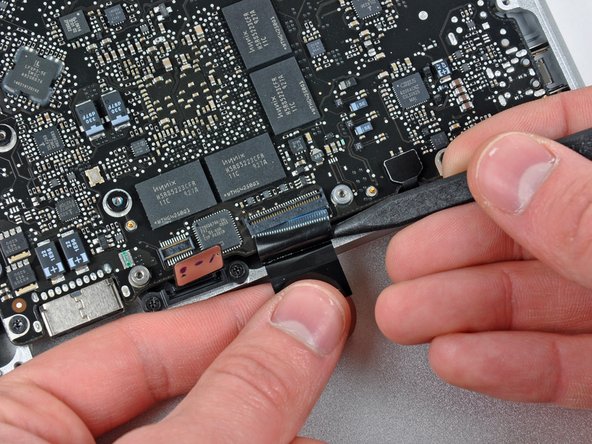
    • When moving the strip (cable retainer) out of the way, be sure not to break any surface-mounted components off the logic board.

    • Hold the end of the cable retainer down with one finger while you use the tip of a spudger to slightly lift the other end and rotate it away from the camera cable connector.

    • Disconnect the camera cable by pulling the male end straight away from its socket.

    • Pull the connector parallel to the face of the logic board, not straight up.

  12. 这个步骤还没有翻译 帮忙翻译一下

    : 步骤 12 中的图像 1,1
    • Disconnect the camera cable by pulling the male end straight away from its socket.

    • Pull the connector parallel to the face of the logic board, not straight up.

  13. 这个步骤还没有翻译 帮忙翻译一下

    : 步骤 13 中的图像 1,1
    • Use the flat end of a spudger to pry the optical drive cable connector up off the logic board.

  14. 这个步骤还没有翻译 帮忙翻译一下

    : 步骤 14 中的图像 1,1
    • Using the flat end of a spudger, pry the subwoofer connector straight up from the connector jack.

    • Be careful to pry the connector, not the socket. It's possible to accidentally pry the socket up from the logic board.

    • Removing the foam applied to the top of the connector will make it easier to see and avoid prying up the socket.

  15. 这个步骤还没有翻译 帮忙翻译一下

    : 步骤 15 中的图像 1,1
    • Use the flat end of a spudger to pry the hard drive/IR sensor cable connector up off the logic board.

  16. 这个步骤还没有翻译 帮忙翻译一下

    : 步骤 16 中的图像 1,2 : 步骤 16 中的图像 2,2
    • Remove the two 1.5 mm Phillips screws securing the cable cover to the logic board.

    • Lift the cable cover out of the upper case.

  17. 这个步骤还没有翻译 帮忙翻译一下

    : 步骤 17 中的图像 1,1
    • Use a spudger to pry the trackpad flex ribbon cable connector up off the logic board.

  18. 这个步骤还没有翻译 帮忙翻译一下

    : 步骤 18 中的图像 1,2 : 步骤 18 中的图像 2,2
    • Use your fingernail to flip up the locking flap on the ZIF socket for the keyboard ribbon cable. The locking flap is located at the opposite side of the socket compared to the keyboard ribbon cable. Hook your fingernail under it and carefully lift it up vertically.

    • Do not attempt to slide the keyboard ribbon cable out of its socket before you have unlocked the ZIF socket. Ribbon cables are fragile and excessive force will easily break them.

    • Use the tip of a spudger to slide the keyboard ribbon cable out of its socket.

  19. 这个步骤还没有翻译 帮忙翻译一下

    : 步骤 19 中的图像 1,1
    • Use a spudger to pry the battery indicator ribbon cable connector up off the logic board.

  20. 这个步骤还没有翻译 帮忙翻译一下

    : 步骤 20 中的图像 1,2 : 步骤 20 中的图像 2,2
    • Remove the single 7 mm Phillips screw securing the display data cable retainer to the upper case.

    • This screw may remain captive in the display data cable ground loop. If replacing the display, be sure to transfer this screw to the new unit.

    • Remove the display data cable retainer from the upper case.

  21. 这个步骤还没有翻译 帮忙翻译一下

    : 步骤 21 中的图像 1,2 : 步骤 21 中的图像 2,2
    • Grab the plastic pull tab secured to the display data cable lock and rotate it toward the DC-in side of the computer.

  22. 这个步骤还没有翻译 帮忙翻译一下

    : 步骤 22 中的图像 1,1
    • Pull the display data cable connector straight away from its socket.

    • Make sure to pull the connector parallel to the face of the logic board, not straight up from its socket.

  23. 这个步骤还没有翻译 帮忙翻译一下

    : 步骤 23 中的图像 1,2 : 步骤 23 中的图像 2,2
    • Using the tip of a spudger, flip up the keyboard backlight ribbon cable retaining flap.

    • Pull the keyboard backlight ribbon cable straight out of its socket.

  24. 这个步骤还没有翻译 帮忙翻译一下

    : 步骤 24 中的图像 1,1
    • Remove the following screws:

    • Seven 3.3 mm T6 Torx screws securing the logic board to the upper case.

    • Two 8 mm T6 Torx screws securing the DC-In board to the upper case.

    • Do not remove the logic board yet! There are components on the underside of the logic board attached to the the upper case that must first be disconnected.

  25. 这个步骤还没有翻译 帮忙翻译一下

    : 步骤 25 中的图像 1,1
    • Carefully lift the logic board assembly from the left side and work it out of the upper case, minding the port side that may get caught during removal.

    • Do not entirely remove the logic board yet!

  26. 这个步骤还没有翻译 帮忙翻译一下

    : 步骤 26 中的图像 1,1
    • Lift the logic board enough to gain clearance and use a spudger to pry the microphone up off the upper case.

    • Slide the logic board away from the port openings and lift the assembly out of the upper case.

    • Before reinstalling the logic board, it is easiest to press the microphone down into its housing in the left speaker to keep it in place.

  27. 这个步骤还没有翻译 帮忙翻译一下

    : 步骤 27 中的图像 1,1
    • Slide the logic board away from the port openings and lift the assembly out of the upper case.

    • Before reinstalling the logic board, it is easiest to press the microphone down into its housing in the left speaker to keep it in place.

  28. 这个步骤还没有翻译 帮忙翻译一下

    : 步骤 28 中的图像 1,1
    • If your microphone is still inserted into its void in the left speaker housing, use the tip of a spudger to lift it out.

  29. 这个步骤还没有翻译 帮忙翻译一下

    : 步骤 29 中的图像 1,1
    • Remove the small strip of tape covering the left speaker connector.

  30. 这个步骤还没有翻译 帮忙翻译一下

    : 步骤 30 中的图像 1,1
    • Use the flat end of a spudger to pry the left speaker connector up off its socket on the logic board.

    • Pry up from beneath the wires.

  31. 这个步骤还没有翻译 帮忙翻译一下

    : 步骤 31 中的图像 1,2 : 步骤 31 中的图像 2,2
    • Remove the two 5 mm Phillips screws securing the left speaker to the logic board.

    • Lift the left speaker off the logic board.

终点

5等其他人完成本指南。

0条评论

添加评论

浏览统计数据:

过去 24 小时: 1

过去 7 天: 10

过去 30 天: 15

总计 9,722