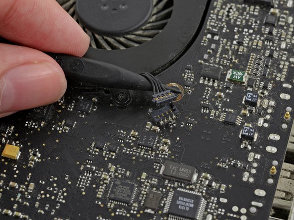
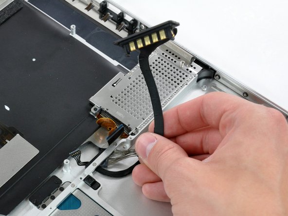
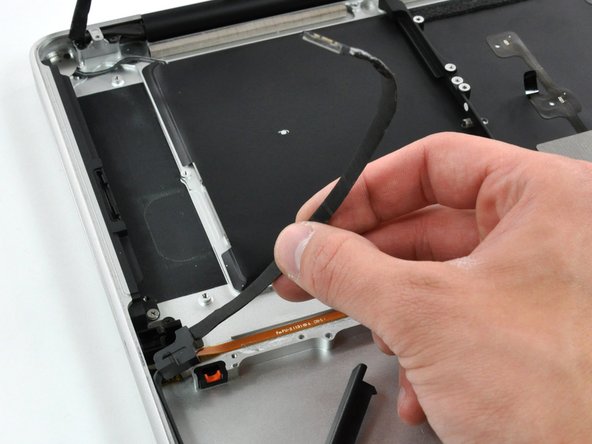
Grab the plastic pull tab secured to the display data cable lock and rotate it toward the DC-in side of the computer.
Pull the display data cable connector straight away from its socket.
When disconnecting the display data cable, do not pull on the black tab secured to the cable lock. We recommend wiggling the cable while applying tension to slowly "walk" the connector out of its socket.
Make sure the display data cable is placed correctly in its socket during reassembly. Failure to do so will result in a partially visible display or no display image at all.
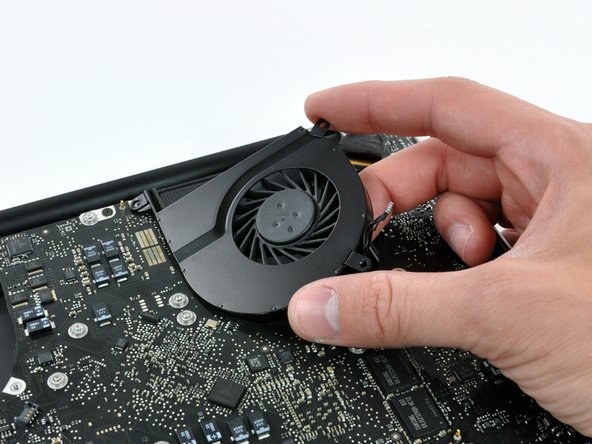
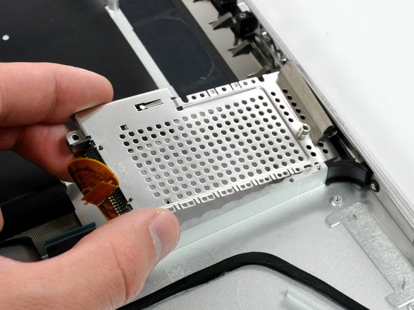
Carefully lift the logic board assembly from the left side and work it out of the upper case, minding the port side that may get caught during removal.
Do not entirely remove the logic board yet!
Ensure that the logic board is free from all connections to the upper case (except the battery connector) before proceeding.
During reassembly, ensure all connectors and cables are not placed underneath the logic board. Some of the ribbon cables are very thin and fragile.
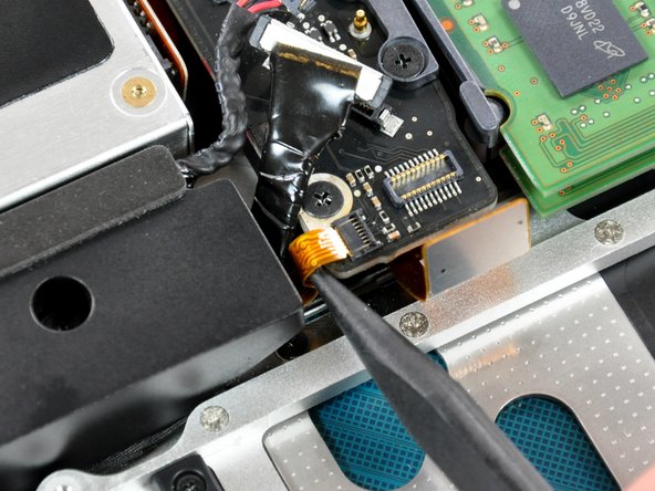
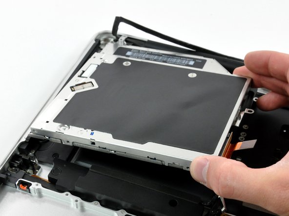
The battery connector cover is held onto the upper case by a strong adhesive. Use a spudger to loosen the adhesive around the edges of the battery connector.
Lift the battery connector cover out of the upper case.
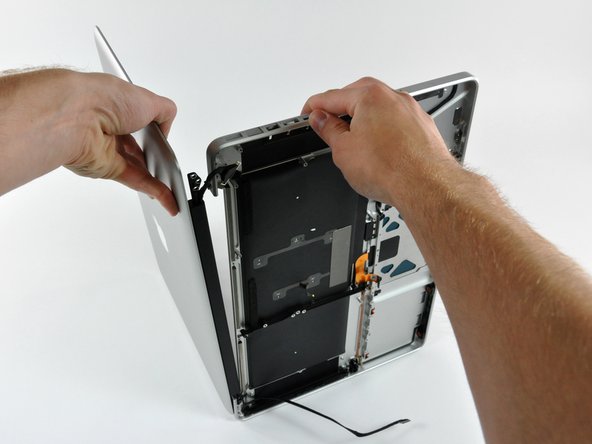
Be sure to hold the display and upper case together with your other hand. Failure to do so may cause the freed display/upper case to fall, potentially damaging each component.
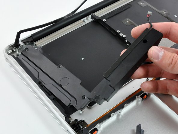
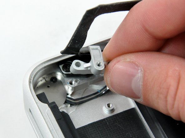
Remove the last remaining 6 mm Torx screw securing the display to the upper case.
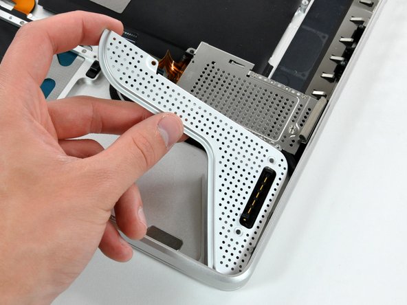
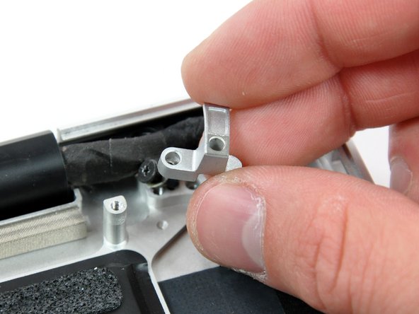
Grab the upper case with your right hand and rotate it slightly toward the top of the display so the upper display bracket clears the edge of the upper case.
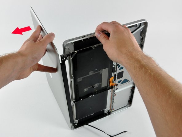
Rotate the display slightly away from the upper case.
Lift the display away from the upper case, minding any brackets or cables that may get caught.