当前版本的文档还未经巡查,您可以查看最新的已查核版本 。
仅作为前提条件
本指南仅用作其他指南的先决条件。不能单独食用。
Remove the following 5 screws securing the mid wall to the upper case:
Three 10.5 mm Phillips screws.
Two 3.7 mm Phillips screws.
Remove the following six screws securing both the right fan and the left fan to the logic board:
Four 3.5 mm Phillips screws.
Two 3.2 mm Phillips screws.
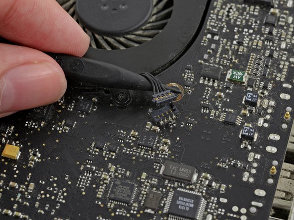
Use the tip of a spudger to lift the right fan connector straight up from its socket on the logic board.
Be sure to only pry up on the connector itself not on the socket or you may damage the machine.
It is useful to twist the spudger axially from beneath the fan cable wires to release the connector.
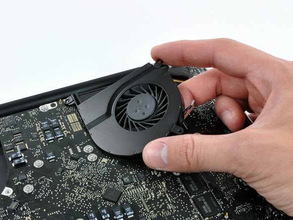
Remove the right fan from the case.
Use the tip of a spudger to lift the left fan connector straight up from its socket on the logic board.
Be sure to only pry up on the connector itself not on the socket or you may damage the machine.
It is useful to twist the spudger axially from beneath the fan cable wires to release the connector.
Remove the left fan from the case.
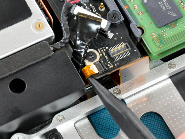
Remove any adhesive from the camera cable connector.
Disconnect the camera cable by pulling the male end out of its socket, parallel to the logic board, do not lift it upwards.
If necessary, peel off the foam bumper covering the subwoofer connector.
Using the flat end of a spudger, pry the subwoofer connector straight up off its socket on the logic board.
Be very careful. This connection is delicate, the socket can be easily broken off the logic board.
Using the tip of a spudger, flip up the IR/sleep LED ribbon cable retaining flap.
Pull the IR/sleep LED ribbon cable straight out of its socket.
Using the tip of a spudger, flip up the keyboard ribbon cable retaining flap.
Pull the keyboard ribbon cable straight out of its socket.
During reassembly, make sure to fully insert the keyboard ribbon cable back into the ZIF socket.
Using the tip of a spudger, flip up the express card cage ribbon cable retaining flap.
Pull the express card cage ribbon cable straight out of its socket.
Using the flat end of a spudger, pry the microphone cable connector straight up out of its socket on the logic board.
Pry up under the cable wires to avoid pulling the socket itself off of the logic board.
Grab the plastic pull tab secured to the display data cable lock and rotate it toward the DC-in side of the computer.
Pull the display data cable connector straight away from its socket.
When disconnecting the display data cable, do not pull on the black tab secured to the cable lock. We recommend wiggling the cable while applying tension to slowly "walk" the connector out of its socket.
Make sure the display data cable is placed correctly in its socket during reassembly. Failure to do so will result in a partially visible display or no display image at all.
Locate the keyboard backlight ribbon cable (near the left fan space).
Using the tip of a spudger, flip up the keyboard backlight ribbon cable retaining flap.
Pull the keyboard backlight ribbon cable straight out of its socket.
Remove seven 3.2 mm Phillips screws securing the logic board to the upper case.
Do not remove the logic board yet! There are connectors attached to the underside of the logic board that must first be disconnected.
Remove two 7 mm Phillips screws securing the DC-in board to the upper case.
Note: This step is not completely necessary, but it will make it easier to disconnect the cable that is connected to the DC-in board.
Remove two 3.5 mm Phillips screws securing the bottom case clip to the upper case.
Lift the bottom case clip out of the upper case.
Some MacBook Pro Unibodies do not have a bottom case clip and do not require this step.
Carefully lift the logic board assembly from the left side and work it out of the upper case, minding the port side that may get caught during removal.
Do not entirely remove the logic board yet!
Ensure that the logic board is free from all connections to the upper case (except the battery connector) before proceeding.
During reassembly, ensure all connectors and cables are not placed underneath the logic board. Some of the ribbon cables are very thin and fragile.
嵌入本指南
选择一个尺寸并复制下面的代码,将本指南作为一个小插件嵌入到你的网站/论坛中。
单个步骤
完整指南
小——600像素
中——800像素
大——1200像素
预览