跳转到主内容

当前版本的文档还未经巡查,您可以查看最新的已查核版本

你所需要的

  1. , 后盖: 步骤 1 中的图像 1,1
    • 将固定 MacBook Pro 后盖的 P5 五角螺丝拆掉:

    • 8颗 3.0mm 螺丝

    • 2颗 2.3mm 螺丝

  2. : 步骤 2 中的图像 1,1
    • 从后盖盖和主机壳夹扣处抬起,从 MacBook Pro上取下后盖。

    • 将取下的后盖放到一边。

  3. , 电池连接器: 步骤 3 中的图像 1,1
    • 揭开盖住电池接口的警告标签。

  4. : 步骤 4 中的图像 1,2 : 步骤 4 中的图像 2,2
    • 使用撬棒平头的那端,轻轻地将电池接口直接从逻辑板上的插座中撬出。

    • 弯曲电池电缆,确保电池接口不会意外接触逻辑板。

  5. , AirPort/相机线缆: 步骤 5 中的图像 1,1
    • 使用撬棒尖端来将三条AirPort天线线缆从 AirPort 板上的插座中径直翘起。

    • 此线缆的连接插口很脆弱。请注意分离位置是在连接器上方链接部分而不是在底插或线缆处。

    • 重新插回时可以在小心的对准插口位置后利用撬棒较宽的平面部分水平发力下按。

  6. : 步骤 6 中的图像 1,1
    • 使用撬棒的尖端来推动相机线缆位于逻辑板插座上的链接头。

    • 照片中的插头有六个接口,但有些型号是有十二个接口。这两种型号拔出插头的过程是相同的。

    • 如果相机排线的插头很难从主板上拔出,请将风扇上的橡胶盖向后折叠使相机排线露出。在轻拉排线的同时使用撬棒将插头轻轻推出插座

    • 请确保推动方向与主板相平行,先推动一侧,然后让链接头从插座中“走”出来。如果强行将其撬起则会有损坏部件的可能。

  7. : 步骤 7 中的图像 1,3 : 步骤 7 中的图像 2,3 : 步骤 7 中的图像 3,3
    • 在右侧散热风扇橡胶垫下方插入撬棒扁平的一端。

    • 在下方滑动,来分离粘合剂。

    • 抬起翻开,你就可以靠近下方的线缆了。

  8. : 步骤 8 中的图像 1,3 : 步骤 8 中的图像 2,3 : 步骤 8 中的图像 3,3
    • 使用手指来将 AirPort和摄像头线缆从风扇上剥离。

    • 线缆粘附于风扇上,所以请小心剥离以免损伤。

    • 小心地将电缆从塑料电缆导轨上卸下。

  9. , 橡胶铰链盖: 步骤 9 中的图像 1,2 , 橡胶铰链盖: 步骤 9 中的图像 2,2
    • 利用撬棒的水平端分别撬起macbook如图所示左右两端的橡胶铰链盖

  10. , 连接显示屏的螺丝拆卸: 步骤 10 中的图像 1,2 , 连接显示屏的螺丝拆卸: 步骤 10 中的图像 2,2
    • 卸下如图中的两颗3.1毫米T5 梅花螺丝,它们是为了将铝制铰链盖固定到C壳上。

    • 从C壳上卸下这两个铝制铰链支架。

  11. , I/O 板线缆: 步骤 11 中的图像 1,3 , I/O 板线缆: 步骤 11 中的图像 2,3 , I/O 板线缆: 步骤 11 中的图像 3,3
    • 如果 I/O 板电缆的连接器在衬垫中有槽口,你需要松开槽口下方的锁定杆以移除电缆。 如果是这种情况,请在拉杆解锁之前不要撬起接口。

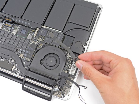
    • 使用撬棒扁平的一端,将 I/O 板连接器从主板上的插座中直接撬出。

    • 在重新组装设备的时候,首先连接这一端,因为它不会弯曲。

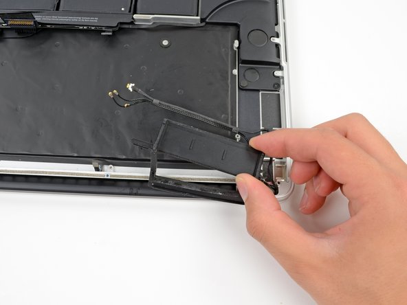
    • 以类似的方式,从 I/O 板上的插槽中卸下 I/O 板排线。

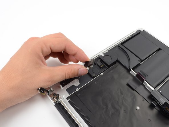
    • 从 MacBook Pro 上拔下 I/O 板电缆。

  12. , Airport卡: 步骤 12 中的图像 1,1
    • 移除一颗将AirPort卡与主板相固定的2.9mm T5 梅花螺丝(有些时候可能是T6)。

  13. : 步骤 13 中的图像 1,2 : 步骤 13 中的图像 2,2
    • 抓住 AirPort 卡的两侧,将其向上以小角度略微提起(5-10˚),以分离粘附在主板上的轻质粘合剂。

    • 将 AirPort 卡平行于主板上的接口拉出以将其卸下。

  14. : 步骤 14 中的图像 1,2 : 步骤 14 中的图像 2,2
    • 使用撬棒的尖端来将右风扇的排线ZIF插座解锁。

    • 请确保您在撬动插座铰链而不是插座本身。

    • 从电缆顶部开始,在右侧风扇电缆下面滑动塑料打开工具,将其从逻辑板上取出。

    • 取出电缆时要小心谨慎,因为它牢固地固定在逻辑板上。

  15. : 步骤 15 中的图像 1,1
    • 拧下固定右侧风扇到主板的三颗螺丝如下:

    • 一颗 4.4mm T5 梅花 螺丝

    • 一颗 3.9mm T5 宽头梅花 螺丝

    • 一颗 5.0mm T5 梅花螺丝 带有一个2mm套管。

  16. : 步骤 16 中的图像 1,1
    • 从MacBook Pro中提起移走右风扇。

    • 装回风扇时,比较简单的方法是先连接风扇电缆,而不是先安装三个风扇螺钉。

  17. , 左侧风扇: 步骤 17 中的图像 1,1
    • 使用撬棒的扁平一端来翘起左侧风扇上的橡胶导热槽。

  18. : 步骤 18 中的图像 1,1
    • 移除下列三颗将左风扇固定在逻辑板上的螺丝。

    • 一颗 4.4mm T5 梅花螺丝,包含一个2mm套管。

    • 一颗 5.0mm T5 梅花螺丝, 包含一个2mm套管。

    • 一颗 3.9mm T5 宽头梅花螺丝。

    • 重新安装风扇及其螺丝钉时,在将全部螺丝钉安装之前,请不要将螺丝钉完全拧紧。这样在将螺帽套到螺丝钉上时,风扇可以略微移动以更好的固定螺帽。

  19. : 步骤 19 中的图像 1,3 : 步骤 19 中的图像 2,3 : 步骤 19 中的图像 3,3
    • 使用撬棒尖端来将风扇排线从ZIF插座上解锁下来。

    • 请确保您在撬动铰链部分而不是插座本身。

    • 从线缆顶部开始,在线缆底部滑入一个塑料打开工具来将线缆从逻辑板上卸下。

    • 卸下电缆时要小心谨慎,因为它牢固地固定在逻辑板上。 如有必要,请使用iOpener或吹风机加热电缆,以便软化粘合剂并使其更易于清除。

    • 从设备上取出左风扇。

    • 装回风扇时,较为简单的方法是先连接风扇电缆,而不是先安装三个风扇螺钉。

  20. , SSD 固态硬盘: 步骤 20 中的图像 1,1
    • 拧下把SSD固态硬盘固定到主板的 3.1 mm T5 Torx 螺丝。

  21. : 步骤 21 中的图像 1,2 : 步骤 21 中的图像 2,2
    • 轻轻提起最右边 SSD 固态硬盘,把它从主板的槽里直接滑出来。

  22. , I/O 板: 步骤 22 中的图像 1,2 , I/O 板: 步骤 22 中的图像 2,2
    • 使用撬棒尖端将I / O板数据电缆锁向上翻,并将其向计算机的电池侧旋转。

    • 使用撬棒的扁平端将I / O板数据电缆从逻辑板上的插槽中滑出。

    • 请勿抬起I / O板数据电缆,因为其插口非常脆弱。 将电缆平行于逻辑板的表面拉动。

  23. : 步骤 23 中的图像 1,3 : 步骤 23 中的图像 2,3 : 步骤 23 中的图像 3,3
    • 移除两颗固定I/O板的3.1mm T5 梅花螺丝。

    • 在某些型号上,还可以从散热器上卸下银色的 3.5 毫米 T5 Torx 螺丝,这有助于卸下 I/O 板。

    • 小心地提起I/O板,并将其从底壳中移除。

  24. , 逻辑板组件: 步骤 24 中的图像 1,1
    • 使用撬棒扁平一端来从逻辑板上翘起耳机孔链接插头。

  25. : 步骤 25 中的图像 1,2 : 步骤 25 中的图像 2,2
    • 使用撬棒扁平一端翘起连接到逻辑板上的左扬声器插头。

    • 使用撬棒的尖端来翘起连接到逻辑板上的右扬声器插头。

    • 请确保撬动线缆头,而不是插座本身。 撬动插座将会导致其与逻辑板分离。

  26. : 步骤 26 中的图像 1,1
    • 剥下覆盖键盘带状电缆连接器的所有胶带。

  27. : 步骤 27 中的图像 1,3 : 步骤 27 中的图像 2,3 : 步骤 27 中的图像 3,3
    • 使用撬棒扁平的一端掀起键盘带状电缆 ZIF 插座上的固定盖板。

    • 只在铰链固定翻盖下方撬动,而不是从插座本身撬动,否则可能会将其从板上折断。

    • 使用撬棒扁平的一端,先推一侧,然后推另一侧,轻轻地将键盘带状电缆从插座中拉出。

  28. : 步骤 28 中的图像 1,1
    • 使用撬棒扁平一端来从逻辑板上的插座中翘起触摸板链接插头。

  29. : 步骤 29 中的图像 1,1
    • 使用撬棒扁平一端来从逻辑板上的插座中翘起键盘背光灯连接插头。

  30. : 步骤 30 中的图像 1,1
    • 使用撬棒或者您的支架来将麦克风排线从ZIF插座上解锁。

    • 请确保您在撬动铰链,而不是插座本身。

    • 将麦克风排线从插座中拉出。

  31. : 步骤 31 中的图像 1,2 : 步骤 31 中的图像 2,2
    • 使用撬棒的尖端来的撬动数显示据电线锁,并将其向计算机的电源接口侧旋转。

    • 将显示数据线直接从逻辑板上的插座中拔出。

    • 请勿抬起显示器的数据线,因为其插口非常脆弱。 将电缆平行于逻辑板的表面拉。

  32. : 步骤 32 中的图像 1,1
    • 使用撬棒扁平一端来小心地撬动靠近MagSafe 2连接器的凸起螺钉头上的橡胶螺帽。

  33. : 步骤 33 中的图像 1,1
    • 移除下列六颗将逻辑板与底壳固定的螺丝。

    • 1颗 2.6mm T5 梅花螺丝

    • 2颗 5.8mm T5 梅花螺丝

    • 1颗 3.8mm T5梅花螺丝

    • 1颗 5.2mm 突头 T5 梅花螺丝

    • 1颗 3.5mm 银 T5 梅花螺丝

  34. : 步骤 34 中的图像 1,3 : 步骤 34 中的图像 2,3 : 步骤 34 中的图像 3,3
    • 从靠近电池一侧朝着MacBook Pro提起逻辑板。

    • 使用撬棒扁平一端,小心地将MagSafe2 链接头从逻辑板中的插座中推出。

    • 重新安装逻辑板时,请检查标记位置的电缆,确保它们不被固定在逻辑板下面。

    • 从顶部顺时针方向:键盘,触控板,电池,右扬声器,键盘背光,显示器,麦克风,耳机插孔,左扬声器。

  35. : 步骤 35 中的图像 1,1
    • 从MacBook Pro 中移出逻辑板组件。

  36. 这个步骤还没有翻译 帮忙翻译一下

    : 步骤 36 中的图像 1,3 : 步骤 36 中的图像 2,3 : 步骤 36 中的图像 3,3
    • Remove the single 2.6 mm T5 Torx screw securing the left rubber hinge cover in place.

    • Slide the hinge cover out of its bezel, then lift it up and out of the device.

    • The screw in the right hinge cover should already have been removed.

    • Slide the right cover out of its bezel, then lift it out of the device.

  37. 这个步骤还没有翻译 帮忙翻译一下

    : 步骤 37 中的图像 1,3 : 步骤 37 中的图像 2,3 : 步骤 37 中的图像 3,3
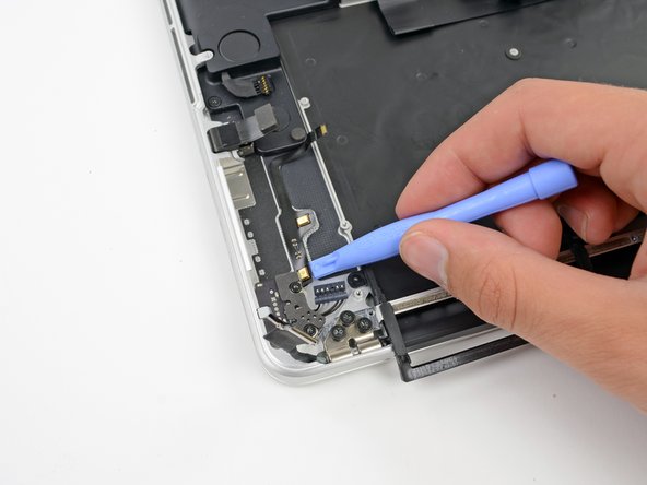
    • Insert the edge of a plastic opening tool underneath the upper microphone.

    • Slide the blade of a plastic opening tool along the bottom of the upper microphone, releasing the adhesive.

    • Be careful when releasing the adhesive holding the cable down, as these cables have been known to tear easily.

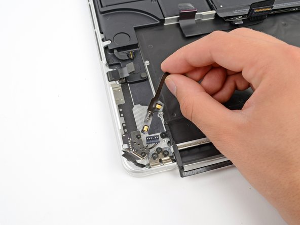
    • In a similar manner, release the adhesive underneath the lower microphone.

    • Lift the cable out of the device.

  38. 这个步骤还没有翻译 帮忙翻译一下

    : 步骤 38 中的图像 1,2 : 步骤 38 中的图像 2,2
    • Remove the two 4.0 mm T5 Torx screws securing the MagSafe DC-In board to the upper case.

    • Slide the MagSafe DC-In board towards the right free it from its recess within the upper case.

    • Lift and remove the MagSafe DC-In board out of the upper case assembly.

  39. 这个步骤还没有翻译 帮忙翻译一下

    : 步骤 39 中的图像 1,2 : 步骤 39 中的图像 2,2
    • Remove the two 3.6 mm T5 Torx screws securing the headphone jack to the upper case assembly.

    • Slide the headphone jack away from the upper case.

    • Lift and remove the headphone jack out from its recess in the upper case.

  40. 这个步骤还没有翻译 帮忙翻译一下

    : 步骤 40 中的图像 1,2 : 步骤 40 中的图像 2,2
    • Remove the following three screws securing the left speaker to the upper case:

    • One 5.6 mm T5 Torx screw

    • One 6.9 mm T5 Torx screw

    • One 2.6 mm T5 Torx screw

    • Lift the left speaker out of the upper case and set it aside.

  41. 这个步骤还没有翻译 帮忙翻译一下

    : 步骤 41 中的图像 1,2 : 步骤 41 中的图像 2,2
    • Remove the following three screws securing the right speaker to the upper case:

    • One 5.6 mm T5 Torx screw

    • One 6.9 mm T5 Torx screw

    • One 2.6 mm T5 Torx screw

    • Remove the right speaker from the MacBook Pro.

  42. 这个步骤还没有翻译 帮忙翻译一下

    : 步骤 42 中的图像 1,1
    • Remove four out of the six 5.3 mm T8 Torx screws securing the display to the upper case.

    • We purposely have you leave two screws attaching the display to the upper case to aid in future steps.

  43. 这个步骤还没有翻译 帮忙翻译一下

    : 步骤 43 中的图像 1,2 : 步骤 43 中的图像 2,2
    • Open the device between 90 and 100 degrees, then rest it on its side.

    • While supporting both halves of the device with one hand, unscrew the upper 5.3 mm T8 Torx screw.

    • Repeat the same process for the identical bottom screw.

    • Be sure to hold the display and upper case together with one hand. Failure to do so may cause the freed display/upper case to fall, potentially damaging each component.

  44. 这个步骤还没有翻译 帮忙翻译一下

    : 步骤 44 中的图像 1,2 : 步骤 44 中的图像 2,2
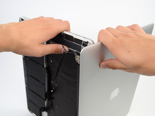
    • Grip both halves of the device. Firmly put one hand on the top center of the upper case (left) and one in the same place on the display assembly (right).

    • While holding the display assembly in place, slowly push forward on the upper case, releasing it from the display assembly.

  45. 这个步骤还没有翻译 帮忙翻译一下

    : 步骤 45 中的图像 1,1
    • Upper case remains.

终点

50等其他人完成本指南。

Jake Devincenzi

于04/18/11注册

117,271 声望

创作了57篇指南

10条评论

How Can I clean a coffee spill on the retina macbook pro? which alcohol to use to clean the logic board and I/O board? Will I get all the necessary tools to open it in Home Tech toolkit?

Neeraj Saini - 回复

Please note a T8 Torx Screwdriver is needed in this guide for the display screws.

rfoppen - 回复

-It would be cool a 3rd party battery manufacturer to make a spare battery without the glue.

-Ony needed to remove the glued one (no prob. if damage it.. it is no good anyway, anymore) and put in place a new one with no glue held in place just by the lack of space inside the case, or some tiny spongy strips to help remove any play.

-The thing is who would manufacture a spare like this.

-Even Apple could supply spares like this.

crus - 回复

I have always turned to iFixIt for repair guides. This particular repair, listed as "difficult," was one that I was apprehensive about undertaking. But I was successful!

I have a brief blog post about it here:

http://www.hightechdad.com/2014/12/22/ho...

And, for those who are going through this guide, I have a LONG (30 minute) video that walks through the repair using the iFixIt guide:

https://www.youtube.com/watch?v=2ODfFSMs...

Hope it helps!

-HTD

HighTechDad - 回复

== The good ==

Very clear instructions, well done.

== The warning ==

There is one major problem though ... I purchased the Upper Case Assembly as mentioned, although from a local retailer in Australia. When I got to the final step, I realised it didn't have the battery or touchpad. If you purchase the case assembly from elsewhere, make sure it comes with the battery/touchpad as these are impossible to move from one unit to another.

carl - 回复

添加评论

浏览统计数据:

过去 24 小时: 2

过去 7 天: 5

过去 30 天: 56

总计 67,358