跳转到主内容

当前版本的文档还未经巡查,您可以查看最新的已查核版本

你所需要的

  1. , 电池: 步骤 1 中的图像 1,1
    • 使用手来推动电池上的电池释放开关,然后将电池从电脑上移走。

  2. , RAM 护板: 步骤 2 中的图像 1,1
    • 移除三颗相同的十字螺丝。

  3. : 步骤 3 中的图像 1,1
    • 向上提起记忆门足高的高度来抓住它,并滑动其,将其从拉出。

  4. , 顶壳: 步骤 4 中的图像 1,1
    • 卸下电池仓闩锁附近的两个2.8 mm Phillips螺丝。

  5. : 步骤 5 中的图像 1,1
    • 移除下列6颗螺丝

    • 两个10 mm T6 Torx螺丝位于RAM插槽的两侧。

    • 四个14.5毫米十字螺丝 位于铰链附近。

  6. : 步骤 6 中的图像 1,1
    • 移除电脑插口附近的四颗3.2 mm Phillips 螺丝。

  7. : 步骤 7 中的图像 1,1
    • 旋转90度,然后移除2颗固定电脑后壳的 3.2 mm Phillips螺丝。

  8. : 步骤 8 中的图像 1,1
    • 再转90度,然后移除侧面的四颗3.2 mm Phillips螺丝。

  9. : 步骤 9 中的图像 1,1
    • 切勿猛拉顶壳,顶壳仍然通过排线与逻辑板相连。

    • 抬起壳子的后部,沿着两边用手指撬动,随着手的移动来撬开顶壳。 一旦松开了两侧,您可能需要上下摆动来释放上部的前部的卡扣(有一些隐藏的塑料卡扣需要“特殊照顾”)。

  10. : 步骤 10 中的图像 1,1
    • 断开触摸板以及键盘连接到逻辑板的排线。

    • 移除顶壳

  11. 这个步骤还没有翻译 帮忙翻译一下

    : 步骤 11 中的图像 1,1
    • Disconnect the three antenna cables attached to the Airport Extreme card.

    • Apple was kind enough to include a label showing where each color antenna cable plugs in - just make sure to look at this when reconnecting the antenna cables.

  12. 这个步骤还没有翻译 帮忙翻译一下

    : 步骤 12 中的图像 1,1
    • Deroute the Airport antenna cables from their channel in the left speaker.

  13. 这个步骤还没有翻译 帮忙翻译一下

    : 步骤 13 中的图像 1,1
    • Disconnect the iSight cable from the logic board by sliding the cable to the left and out of its connector.

  14. 这个步骤还没有翻译 帮忙翻译一下

    : 步骤 14 中的图像 1,1
    • Disconnect the inverter cable from the logic board by placing a spudger beneath the cable and lifting up.

  15. 这个步骤还没有翻译 帮忙翻译一下

    : 步骤 15 中的图像 1,1
    • Disconnect the display data cable from the logic board by pulling sideways.

  16. 这个步骤还没有翻译 帮忙翻译一下

    : 步骤 16 中的图像 1,1
    • Remove the silver T6 Torx securing the ground loop in the display data cable to the casing.

  17. 这个步骤还没有翻译 帮忙翻译一下

    : 步骤 17 中的图像 1,1
    • Support the display with one hand while removing the following 3 screws:

    • Two 9.5 mm silver T6 Torx screws with threads on only part of the shaft on the inside of the display hinges.

    • One 9.5 mm silver T6 Torx screw with threads on the entire shaft on the outside of the left hinge.

  18. 这个步骤还没有翻译 帮忙翻译一下

    : 步骤 18 中的图像 1,1
    • Grasp the display assembly on both sides and lift it up and out of the computer.

  19. 这个步骤还没有翻译 帮忙翻译一下

    : 步骤 19 中的图像 1,2 : 步骤 19 中的图像 2,2
    • Remove the two 5 mm Phillips screws from the lower left and right corners of the display (two screws total).

  20. 这个步骤还没有翻译 帮忙翻译一下

    : 步骤 20 中的图像 1,3 : 步骤 20 中的图像 2,3 : 步骤 20 中的图像 3,3
    • Insert the flat end of a spudger perpendicular to the face of the display between the plastic strip attached to the rear bezel and the front bezel.

    • Do not insert your spudger between the plastic strip and the rear bezel.

    • With the spudger still inserted, rotate it away from the display to separate the front and rear bezels.

    • Work along the left edge of the display until the rear bezel is evenly separated from the front bezel.

  21. 这个步骤还没有翻译 帮忙翻译一下

    : 步骤 21 中的图像 1,3 : 步骤 21 中的图像 2,3 : 步骤 21 中的图像 3,3
    • Insert the flat end of a spudger perpendicular to the face of the display between the plastic strip attached to the rear bezel and the front bezel.

    • With the spudger still inserted, rotate it away from the display to separate the front and rear bezels.

    • Work along the right edge of the display until the rear bezel is evenly separated from the front bezel.

  22. 这个步骤还没有翻译 帮忙翻译一下

    : 步骤 22 中的图像 1,3 : 步骤 22 中的图像 2,3 : 步骤 22 中的图像 3,3
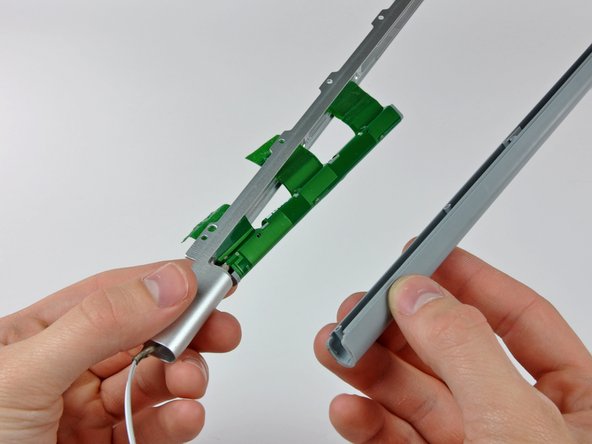
    • Insert the flat end of a spudger between the front bezel and the plastic strip attached to the rear bezel near the screw holes at the bottom corners of the display.

    • Rotate your spudger toward the rear bezel to separate it from the front bezel.

    • If necessary, enlarge the gap between the lower edge of the rear bezel and the clutch cover until the two components are completely separated.

  23. 这个步骤还没有翻译 帮忙翻译一下

    : 步骤 23 中的图像 1,1
    • Lift the rear bezel by its bottom edge and rotate it away from the display assembly to separate the top edge.

    • Remove the rear display bezel from the display assembly.

  24. 这个步骤还没有翻译 帮忙翻译一下

    : 步骤 24 中的图像 1,1
    • The display inverter is a very thin and delicate circuit board that is easily broken. Use caution when handling.

    • Carefully lift the inverter board out of the clutch cover.

  25. 这个步骤还没有翻译 帮忙翻译一下

    : 步骤 25 中的图像 1,1
    • Disconnect the LCD backlight from the inverter by pulling its connector away from the inverter board.

  26. 这个步骤还没有翻译 帮忙翻译一下

    : 步骤 26 中的图像 1,1
    • Be cautious to not put any strain on the inverter cable ground loop, as it is a very thin and delicate wire.

    • Disconnect the inverter cable by pulling its connector away from the socket on the inverter.

  27. 这个步骤还没有翻译 帮忙翻译一下

    : 步骤 27 中的图像 1,2 : 步骤 27 中的图像 2,2
    • Remove the pieces of yellow kapton tape from the bottom left corner of the display.

    • Peel the three green antenna ground straps off the copper tape along the bottom edge of the LCD.

    • The adhesive connecting these straps to the display is very strong. An edged tool is helpful to separate the adhesive while you peel the straps off.

    • Remove the piece of tape securing the camera cable to the LCD.

  28. 这个步骤还没有翻译 帮忙翻译一下

    : 步骤 28 中的图像 1,2 : 步骤 28 中的图像 2,2
    • Remove the pieces of tape covering the display data cable and camera cable connectors.

    • Carefully peel the camera cable off the foam tape along the top edge of the LCD.

  29. 这个步骤还没有翻译 帮忙翻译一下

    : 步骤 29 中的图像 1,2 : 步骤 29 中的图像 2,2
    • Gently pull the camera cable away from its socket on the camera board.

    • Pull the display data cable connector away from its socket on the LCD.

    • Pull both cables parallel to the face of the logic board.

  30. 这个步骤还没有翻译 帮忙翻译一下

    : 步骤 30 中的图像 1,2 : 步骤 30 中的图像 2,2
    • If you have a Core Duo machine, refer to picture 1 and remove three Phillips screws connecting the clutch assembly to the lower edge of the front display bezel near the display data cable.

    • If you have a Core 2 Duo Model A1211 machine, refer to picture 2 and remove two Phillips screws connecting the clutch assembly to the lower edge of the front display bezel near the display data cable.

  31. 这个步骤还没有翻译 帮忙翻译一下

    : 步骤 31 中的图像 1,1
    • Remove the small Phillips screw from behind the display data cable.

    • Remove the small rectangular steel bracket by sliding it away from the right clutch hinge.

    • If you have a Core 2 Duo Model A1211, there is no steel bracket. Simply remove the screw and continue to the next step.

  32. 这个步骤还没有翻译 帮忙翻译一下

    : 步骤 32 中的图像 1,1
    • Remove three Phillips screws attaching the clutch assembly to the lower edge of the front display bezel.

    • The inverter cable ground loop is a very thin and delicate wire. Work gently.

  33. 这个步骤还没有翻译 帮忙翻译一下

    : 步骤 33 中的图像 1,2 : 步骤 33 中的图像 2,2
    • Push the open edge of the clutch cover away from the left clutch hinge to pop it off the clips attaching the two parts.

    • If necessary, repeat this process for the right side of the clutch assembly.

    • Remove the clutch assembly from the front display bezel.

  34. 这个步骤还没有翻译 帮忙翻译一下

    : 步骤 34 中的图像 1,1
    • Remove the five small Phillips screw securing the plastic antenna cover to the inside of the clutch cover.

  35. 这个步骤还没有翻译 帮忙翻译一下

    : 步骤 35 中的图像 1,2 : 步骤 35 中的图像 2,2
    • Pull the antenna cover off the clutch cover, being careful not to damage the antenna cables.

  36. 这个步骤还没有翻译 帮忙翻译一下

    : 步骤 36 中的图像 1,1
    • Remove the antenna cables from the clutch cover, minding the antenna connectors that may get caught on the clutch cover.

终点

另外一个人完成了本指南。

一条评论

Great job on the guide for replacing the WIFI antenna, it is very detailed and informative.

Jose Francisco Medeiros - 回复

添加评论

浏览统计数据:

过去 24 小时: 2

过去 7 天: 2

过去 30 天: 9

总计 5,676