Use a spudger to pry the fan connector out of its seat, and straight up off the logic board.
It is useful to twist the spudger axially from beneath the fan cable wires to release the connector.
The fan socket and the fan connector can be seen in the second and third pictures. Be careful not to break the plastic fan socket off the logic board as you use your spudger to lift the fan connector straight up and out of its socket. The layout of the logic board shown in the second picture may look slightly different than your machine but the fan socket is the same.
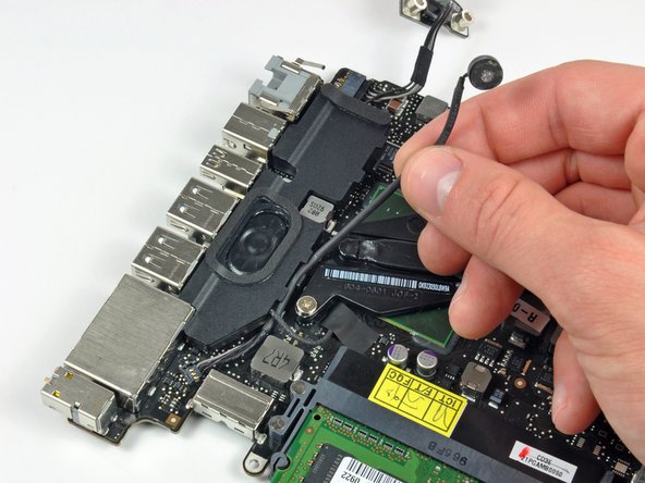
In this step you will disconnect the camera cable. Most machines will have a small self adhesive plastic retainer stuck to the logic board to keep the connector in place. Before disconnecting the cable, be sure this retainer is moved out of the way.
Pull the camera cable connector toward the optical drive to disconnect it from the logic board.
This socket is metal and easily bent. Be sure to align the connector with its socket on the logic board before mating the two pieces.