跳转到主内容

当前版本的文档还未经巡查,您可以查看最新的已查核版本

你所需要的

  1. , Macbook 背盖: 步骤 1 中的图像 1,1
    在这个步骤中使用的工具:
    Magnetic Project Mat
    $19.95
    购买
    • 将固定在顶盖和背盖的螺丝卸除:

    • 两个 2.3mm的P5五角螺丝

    • 八个3.0mm的P5五角螺丝

    • 在整个维修过程中,这款磁性工作垫可以让每颗螺丝都能被磁力吸附,以帮助你将这些螺丝正确地安装回去,以免损坏设备。

  2. : 步骤 2 中的图像 1,1
    • 将手指伸入顶盖和背盖之间。

    • 轻轻地将背盖与顶盖拉开。

    • 将取下的背盖放置在一旁。

  3. : 步骤 3 中的图像 1,3 : 步骤 3 中的图像 2,3 : 步骤 3 中的图像 3,3
    • 背盖和顶盖通过中心的两个塑料夹扣相连。

    • 重新组装的过程中,轻按两个塑料夹扣重新连接。

  4. 这个步骤还没有翻译 帮忙翻译一下

    : 步骤 4 中的图像 1,1
    • Remove the plastic cover adhered to the battery contact board.

  5. 这个步骤还没有翻译 帮忙翻译一下

    : 步骤 5 中的图像 1,1
    • Remove the following screws securing the battery connector board to the logic board:

    • Two 2.8 mm T6 Torx screws

    • One 7.0 mm T6 Torx shouldered screw

  6. 这个步骤还没有翻译 帮忙翻译一下

    : 步骤 6 中的图像 1,2 : 步骤 6 中的图像 2,2
    • Use tweezers to remove the small plastic cover located near the bottom right of the battery connector board.

  7. 这个步骤还没有翻译 帮忙翻译一下

    : 步骤 7 中的图像 1,1
    • Remove the wide head 6.4 mm T6 Torx screw securing the battery connector to the logic board assembly.

  8. 这个步骤还没有翻译 帮忙翻译一下

    : 步骤 8 中的图像 1,2 : 步骤 8 中的图像 2,2
    • Carefully lift the battery connector board up off the logic board.

    • It is recommended to bend the battery cables just slightly, to keep the board suspended up above the logic board and out of the way.

    • Do not fold the board completely over, or crease the cables, as this may damage the battery.

  9. 这个步骤还没有翻译 帮忙翻译一下

    : 步骤 9 中的图像 1,2 : 步骤 9 中的图像 2,2
    • Grasp the Interposer with tweezers.

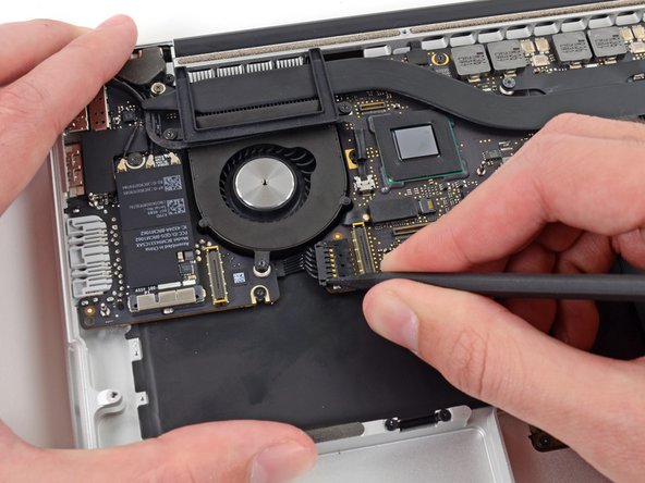
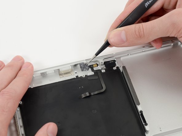
    • An interposer is the name for an interface that links one electrical connection to another. In this repair, it is the board connecting the battery to logic board.

    • Lift the Interposer off the logic board and remove it.

    • Removing this board will ensure that the battery remains disconnected throughout your repair, preventing your computer from accidentally powering on. It's also a good idea to take it out so it doesn't fall out unexpectedly.

  10. 这个步骤还没有翻译 帮忙翻译一下

    : 步骤 10 中的图像 1,2 : 步骤 10 中的图像 2,2
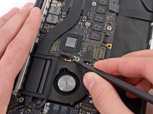
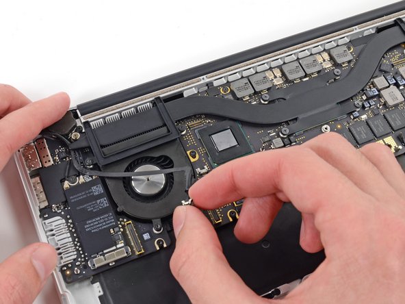
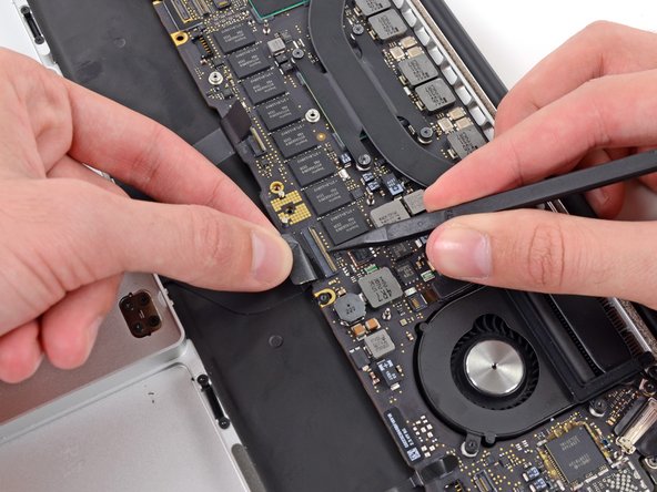
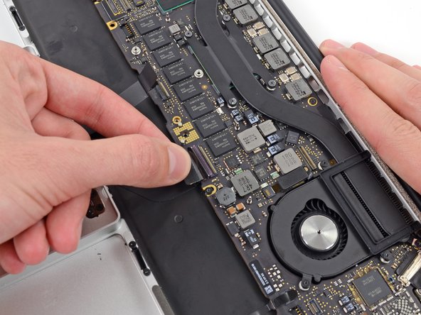
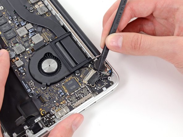
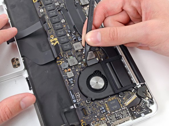
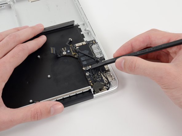
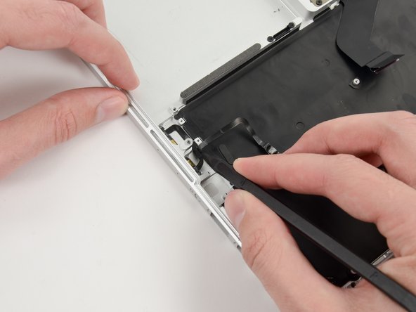
    • Use the flat end of a spudger to pry the right side of the I/O board data cable connector up off its socket on the I/O board.

    • When prying the I/O board data cable connector from its socket, make sure to pry the connector itself and not the socket. Prying the socket may cause irreversible damage to the I/O board.

  11. 这个步骤还没有翻译 帮忙翻译一下

    : 步骤 11 中的图像 1,2 : 步骤 11 中的图像 2,2
    • Wedge the flat end of a spudger beneath the left side of the I/O board data cable connector.

    • Gently twist the spudger to disconnect the I/O board data cable connector from its socket on the logic board.

  12. 这个步骤还没有翻译 帮忙翻译一下

    : 步骤 12 中的图像 1,1
    • Lift and remove the I/O board data cable from the MacBook Pro.

  13. 这个步骤还没有翻译 帮忙翻译一下

    : 步骤 13 中的图像 1,3 : 步骤 13 中的图像 2,3 : 步骤 13 中的图像 3,3
    • Use the flat end of a spudger to pry the SSD cable connector up from its socket on the logic board.

    • Move the SSD cable connector out of the way.

  14. 这个步骤还没有翻译 帮忙翻译一下

    : 步骤 14 中的图像 1,2 : 步骤 14 中的图像 2,2
    • Wedge the pointed end of a spudger beneath the right speaker cable connector.

    • Gently pry the right speaker cable connector up off from its socket on the logic board.

    • Be sure you are prying up on the connector, not the socket itself.

  15. 这个步骤还没有翻译 帮忙翻译一下

    : 步骤 15 中的图像 1,2 : 步骤 15 中的图像 2,2
    • Use a T5 Torx driver to remove the following screws securing the right speaker to the upper case:

    • One black 6.8 mm screw

    • One silver 6.3 mm screw

    • One black 4.9 mm screw

    • The silver screw (in the corner) may be covered with a foam pad. If so, use your tweezers to peel it up and remove it.

  16. 这个步骤还没有翻译 帮忙翻译一下

    : 步骤 16 中的图像 1,2 : 步骤 16 中的图像 2,2
    • Lift and remove the right speaker out of the upper case.

    • If necessary, de-route the right speaker cable from its channel in the upper case.

  17. 这个步骤还没有翻译 帮忙翻译一下

    : 步骤 17 中的图像 1,3 : 步骤 17 中的图像 2,3 : 步骤 17 中的图像 3,3
    • Use the flat end of a spudger to pry the headphone jack cable connector straight up off its socket on the logic board.

    • Gently bend the headphone jack cable to 90° up from the logic board.

    • Bending the headphone jack cable will allow you to disconnect the left speaker cable connector without having the headphone jack cable in the way.

  18. 这个步骤还没有翻译 帮忙翻译一下

    : 步骤 18 中的图像 1,2 : 步骤 18 中的图像 2,2
    • Wedge the tip of a spudger beneath the left speaker cable connector.

    • Gently pry the left speaker cable connector up off from its socket on the logic board.

    • Be sure you are prying up on the connector, not the socket itself.

  19. 这个步骤还没有翻译 帮忙翻译一下

    : 步骤 19 中的图像 1,1
    • Use a T5 Torx driver to remove the following screws securing the left speaker to the upper case:

    • One black 6.8 mm screw

    • One silver 6.3 mm screw

    • One black 4.9 mm screw

    • The silver screw (in the corner) may be covered with a foam pad. If so, use your tweezers to peel it up and remove it.

  20. 这个步骤还没有翻译 帮忙翻译一下

    : 步骤 20 中的图像 1,2 : 步骤 20 中的图像 2,2
    • Lift and remove the left speaker out of the upper case.

  21. 这个步骤还没有翻译 帮忙翻译一下

    : 步骤 21 中的图像 1,3 : 步骤 21 中的图像 2,3 : 步骤 21 中的图像 3,3
    • Use your thumb or finger to bend the plastic spring bar on the SSD tray, freeing the two clips at the front side of the device.

    • While holding the spring bar depressed, tilt the SSD assembly up out of its cavity.

  22. 这个步骤还没有翻译 帮忙翻译一下

    : 步骤 22 中的图像 1,1
    • Remove the SSD assembly from the upper case.

  23. , 电池: 步骤 23 中的图像 1,2 , 电池: 步骤 23 中的图像 2,2
    • 从电池两侧卸下三个 2.2 mm T5 Torx螺丝(总共六个螺丝)。

  24. : 步骤 24 中的图像 1,1
    • 套件中提供的液体粘合剂去除剂会影响MacBook Pro 显示屏上的抗反射涂层。

    • 为了保护你的显示器,请在显示器和键盘之间放置一张铝箔,并在工作时将其留在那里。

  25. : 步骤 25 中的图像 1,2 : 步骤 25 中的图像 2,2
    • 现在你的MacBook Pro已经完全准备好了。下面该准备你自己了。

    • IFixit除胶剂包含丙酮,它会刺激中性皮肤和眼睛。

    • 在涂除胶剂的时候戴一个护目镜。(护目镜包含在你的工具包里。)

    • 没戴护目镜就不要戴隐形眼镜。

    • 防水手套也包含在你的工具包里。如果你担心除胶剂可能刺激你的皮肤,马上戴好手套。

  26. : 步骤 26 中的图像 1,3 : 步骤 26 中的图像 2,3 : 步骤 26 中的图像 3,3
    • 从你的粘合剂去除剂瓶中取下黑色橡胶塞。

    • 在切割涂抹器尖端之前拧开以松开或取下瓶盖。

    • 这会打开瓶子并在切割涂抹器尖端之前使压力均衡。如果跳过此步骤,粘合剂去除器可能会在切割尖端时意外喷出。

    • 用剪刀剪掉涂抹器的密封尖端。

    • 靠近狭窄的尖端切割将使您获得更好的控制,因此您可以少量使用粘合剂去除剂。

    • 在进一步操作之前,请拧紧并关闭瓶盖。

  27. : 步骤 27 中的图像 1,1
    • 向最靠近风扇的电池组的前部边缘下面涂少量的除胶剂。

    • 你不需要使用太多。小瓶子含有的溶剂量是拆除所有电池所需溶剂量的两倍以上。

    • 在继续下步之前,等待2-3分钟,等液体粘合剂去除剂完全渗透电池组。

  28. : 步骤 28 中的图像 1,3 : 步骤 28 中的图像 2,3 : 步骤 28 中的图像 3,3
    • 将撬棒或塑料卡的扁平边缘插入最左侧电池组下方。

    • 沿着电池组的底部周边运行工具并抬起以开始分离粘合剂。

  29. : 步骤 29 中的图像 1,3 : 步骤 29 中的图像 2,3 : 步骤 29 中的图像 3,3
    • 沿着最左边的电池单元的左侧插入撬棒。

    • 沿着最左边的电池单元的左侧向上撬动撬棒。

    • 略微撬动最左边的电池单元,使其从粘合剂中释放出来。

  30. : 步骤 30 中的图像 1,3 : 步骤 30 中的图像 2,3 : 步骤 30 中的图像 3,3
    • 重复上述步骤,将相邻的电池单元与其粘合剂分开:

    • 在电池单元下面滴几滴液体粘合剂去除剂。

    • 等待2-3分钟,使粘合剂去除剂渗透并软化粘合剂。

    • 小心地将撬棒或塑料卡向内楔入,小心不要损坏电池,并将电池与粘合剂分开,将其固定在MacBook Pro上。

  31. : 步骤 31 中的图像 1,3 : 步骤 31 中的图像 2,3 : 步骤 31 中的图像 3,3
    • 将撬棒的扁平端插入较大的最左侧电池单元下方。

    • 小心地将撬棒插入内部,小心不要损坏电池。

    • 将较大的最左边的电池单元从上壳撬起。

  32. : 步骤 32 中的图像 1,3 : 步骤 32 中的图像 2,3 : 步骤 32 中的图像 3,3
    • 抓住电池单元,轻轻移动(但不要将它们)从上壳中的凹槽中移开。

    • 将电池放在上壳顶部,如第三张图所示。

  33. : 步骤 33 中的图像 1,3 : 步骤 33 中的图像 2,3 : 步骤 33 中的图像 3,3
    • 切换侧面并对 MacBook Pro 右侧的两个电池单元重复上述步骤。

    • 请记住在每个电池单元下面添加少量液体粘合剂去除剂,并等待2-3分钟使其渗透,然后撬起电池。

    • 小心不要刺穿或以其他方式损坏电池。

  34. : 步骤 34 中的图像 1,3 : 步骤 34 中的图像 2,3 : 步骤 34 中的图像 3,3
    • 举起并拿走电池。

    • 在你安装你的新电池之前,先从MacBook Pro机身上铲掉所有胶。

    • 如果你有些小运气,你没准儿能用你的手指将那些胶慢慢撕掉。

    • 不然,你就得用除胶剂浸泡每一块胶2、3分钟,然后再用塑料工具将他们刮掉。这会占用你相当长的一段工服,耐心点儿。

    • 擦掉任何残留的除胶剂,再给你的MacBook Pro一点时间晾干它。

    • 你IFixit工具包里的备用电池上事先已经带有胶。在你揭掉胶上的封条之前先仔细地对照一下电池与机身位置是否合适,然后再把每个电池组严整地粘在它应在的位置上。如果你的新电池上有些多余的胶条在你原来的电池上未曾出现,马上移除它们。

    • 在你使用的电池之前先 校准 它:将其充电至100%,并继续充电至少2小时。拔下电源并正常使用以排空电池。当您看到低电量警告时,请保存您的工作,并保持笔记本电脑一直打开,直到它因电池电量不足而进入睡眠状态。等待至少5个小时,然后不间断地将笔记本电脑充电至100%。

    • 在你安装好你的新电池之后,如果你注意到任何不寻常的举动或是问题,你可能需要重置你MacBook Pro的SMC

  35. 这个步骤还没有翻译 帮忙翻译一下

    : 步骤 35 中的图像 1,2 : 步骤 35 中的图像 2,2
    • Use the tip of a spudger to push the edges of the I/O board connector straight out of its socket on the logic board.

    • It is recommended to carefully push on both sides of the connector to "walk" it out of its socket.

  36. 这个步骤还没有翻译 帮忙翻译一下

    : 步骤 36 中的图像 1,2 : 步骤 36 中的图像 2,2
    • Use the tip of a spudger to push the iSight camera cable connector straight away from its socket on the logic board.

    • It is recommended to carefully push on both sides of the connector to "walk" it out of its socket.

  37. 这个步骤还没有翻译 帮忙翻译一下

    : 步骤 37 中的图像 1,2 : 步骤 37 中的图像 2,2
    • Move the iSight camera cable aside.

  38. 这个步骤还没有翻译 帮忙翻译一下

    : 步骤 38 中的图像 1,2 : 步骤 38 中的图像 2,2
    • Wedge the flat end of a spudger underneath the keyboard backlight connector and the logic board.

    • Gently twist the flat end of a spudger upwards to pry the keyboard backlight connector up off its socket on the logic board.

  39. 这个步骤还没有翻译 帮忙翻译一下

    : 步骤 39 中的图像 1,2 : 步骤 39 中的图像 2,2
    • Use the tip of a spudger to flip up the retaining flap on the trackpad ribbon cable ZIF socket.

    • Be sure you are prying up on the hinged retaining flap, not the socket itself.

    • Grasp the plastic pull tab and pull the trackpad ribbon cable out of its socket.

  40. 这个步骤还没有翻译 帮忙翻译一下

    : 步骤 40 中的图像 1,3 : 步骤 40 中的图像 2,3 : 步骤 40 中的图像 3,3
    • Use the tip of a spudger to flip up the retaining flap on the keyboard ribbon cable ZIF socket.

    • Be sure you are prying up on the hinged retaining flap, not the socket itself.

    • Grasp the plastic pull tab and pull the keyboard ribbon cable out of its socket.

  41. 这个步骤还没有翻译 帮忙翻译一下

    : 步骤 41 中的图像 1,3 : 步骤 41 中的图像 2,3 : 步骤 41 中的图像 3,3
    • Use the tip of a spudger to flip up the retaining flap on the microphone ribbon cable ZIF socket.

    • Be sure you are prying up on the hinged retaining flap, not the socket itself.

    • Grasp the plastic pull tab and pull the microphone ribbon cable out of its socket.

  42. 这个步骤还没有翻译 帮忙翻译一下

    : 步骤 42 中的图像 1,2 : 步骤 42 中的图像 2,2
    • Use the tip of a spudger to rotate the pull tab secured to the display data cable lock toward the DC-In side of the computer.

  43. 这个步骤还没有翻译 帮忙翻译一下

    : 步骤 43 中的图像 1,3 : 步骤 43 中的图像 2,3 : 步骤 43 中的图像 3,3
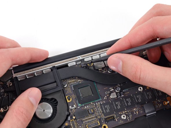
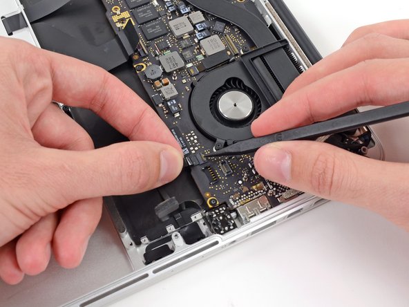
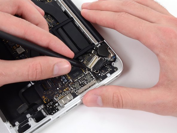
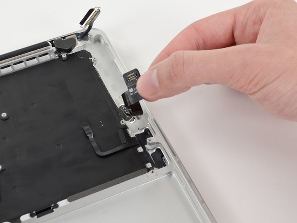
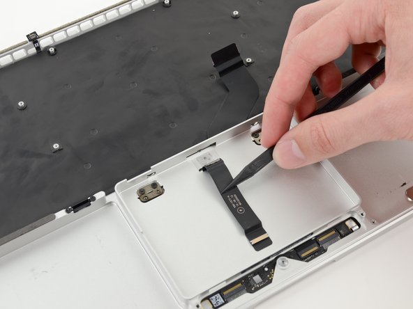
    • Gently push the edges of the display data cable connector away from its socket on the logic board.

    • It is recommended "walk" the connector out of its socket. Simply push the top and bottom corners of the connector and carefully "walk it out" of its socket.

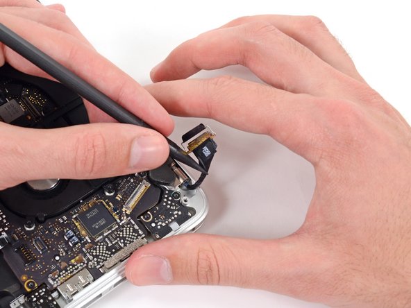
    • Pull, but do not remove, the display data cable connector out of its socket and carefully move it out of the way.

  44. 这个步骤还没有翻译 帮忙翻译一下

    : 步骤 44 中的图像 1,3 : 步骤 44 中的图像 2,3 : 步骤 44 中的图像 3,3
    • Use the tip of a spudger to flip up the retaining flap on the left fan ribbon cable ZIF socket.

    • Be sure you are prying up on the hinged retaining flap, not the socket itself.

    • Carefully pull the left fan ribbon cable out of its socket.

  45. 这个步骤还没有翻译 帮忙翻译一下

    : 步骤 45 中的图像 1,1
    • Move the left fan ribbon cable aside to reveal a hidden screw securing the logic board assembly to the upper case.

  46. 这个步骤还没有翻译 帮忙翻译一下

    : 步骤 46 中的图像 1,2 : 步骤 46 中的图像 2,2
    • Remove the following screws securing the logic board to the upper case:

    • Eight 3.3 mm T5 Torx screws

    • One Phillips #00 screw

    • Two 3.1 mm T5 Torx screws

    • Remove two more screws, from the MagSafe DC-In board in the upper right corner (second image).

    • Two 3.4 mm T5 Torx screws

  47. 这个步骤还没有翻译 帮忙翻译一下

    : 步骤 47 中的图像 1,2 : 步骤 47 中的图像 2,2
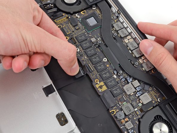
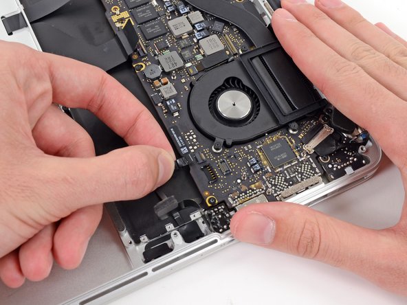
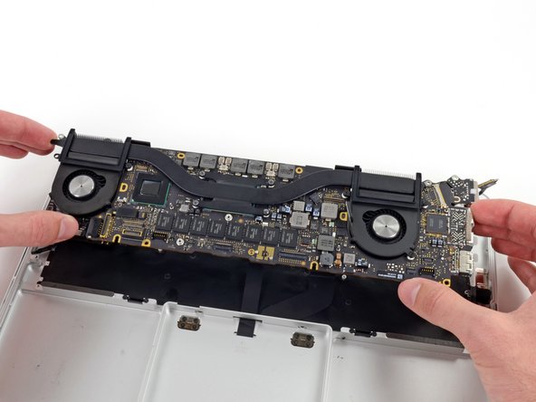
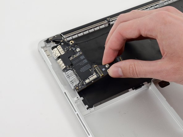
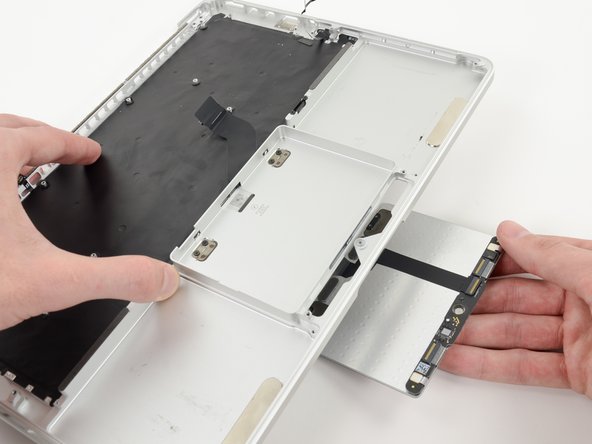
    • Carefully lift the logic board assembly from its left side and work it out of the upper case, minding any cables and the I/O ports that may get caught during removal.

    • Pull the right I/O port side of the logic board away from the side of the upper case and remove the logic board assembly.

  48. 这个步骤还没有翻译 帮忙翻译一下

    : 步骤 48 中的图像 1,3 : 步骤 48 中的图像 2,3 : 步骤 48 中的图像 3,3
    • Use the flat end of a spudger to pry and disconnect the three antenna cable connectors from the AirPort board.

    • The three cables are coded with black sleeves of different lengths. During reassembly:

    • Connect the long-sleeved cable to the center socket.

    • The short-sleeved cable connects next to the screw.

    • The remaining cable has no sleeve, and connects in the last empty socket, next to the fan.

  49. 这个步骤还没有翻译 帮忙翻译一下

    : 步骤 49 中的图像 1,1
    • Remove the following two screws securing the I/O board to the upper case:

    • One 3.53 mm T5 Torx screw

    • One 4.89 mm T8 Torx standoff screw

  50. 这个步骤还没有翻译 帮忙翻译一下

    : 步骤 50 中的图像 1,2 : 步骤 50 中的图像 2,2
    • Carefully pull and remove the I/O board away from its recess in the upper case.

  51. 这个步骤还没有翻译 帮忙翻译一下

    : 步骤 51 中的图像 1,1
    • Remove the two 3.4 mm T5 Torx screws securing the headphone jack to the upper case.

  52. 这个步骤还没有翻译 帮忙翻译一下

    : 步骤 52 中的图像 1,2 : 步骤 52 中的图像 2,2
    • Lift and remove the headphone jack out of the upper case.

  53. 这个步骤还没有翻译 帮忙翻译一下

    : 步骤 53 中的图像 1,2 : 步骤 53 中的图像 2,2
    • Use a pair of tweezers to lift the rubber hinge covers up off the right and left display hinges.

  54. 这个步骤还没有翻译 帮忙翻译一下

    : 步骤 54 中的图像 1,2 : 步骤 54 中的图像 2,2
    • Remove the 3.2 mm T5 Torx screws (one on each side) securing the aluminum hinge brackets to the upper case.

  55. 这个步骤还没有翻译 帮忙翻译一下

    : 步骤 55 中的图像 1,2 : 步骤 55 中的图像 2,2
    • Use a pair of tweezers to lift aluminum hinge brackets off the right and left display hinges.

  56. 这个步骤还没有翻译 帮忙翻译一下

    : 步骤 56 中的图像 1,2 : 步骤 56 中的图像 2,2
    • Remove the four inner 5.3 mm T8 Torx screws (two on each side) securing the display to the upper case.

  57. 这个步骤还没有翻译 帮忙翻译一下

    : 步骤 57 中的图像 1,2 : 步骤 57 中的图像 2,2
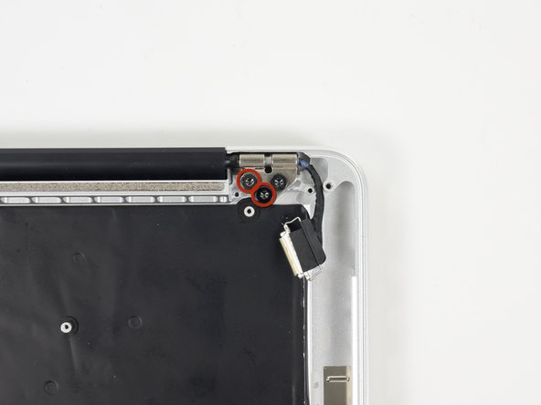
    • Open the MacBook Pro approximately 110 degrees, and place it sideways on the table, as shown.

    • While holding the display and upper case together with your left hand, remove the remaining T8 Torx screw from the lower display bracket.

    • Be sure to hold the display and upper case together with your left hand. Failure to do so may cause the freed display/upper case to fall, potentially damaging each component.

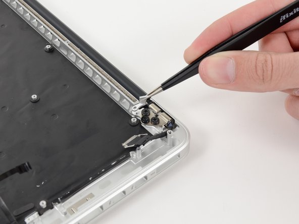
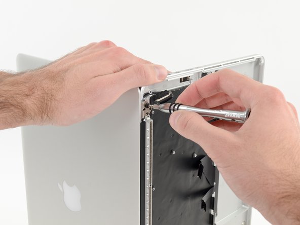
    • Remove the last remaining T8 Torx screw securing the display to the upper case.

  58. 这个步骤还没有翻译 帮忙翻译一下

    : 步骤 58 中的图像 1,3 : 步骤 58 中的图像 2,3 : 步骤 58 中的图像 3,3
    • Grip both halves of the device, one in each hand.

    • Gently push forward on the bottom half of the device to detach it from the display assembly.

    • Carefully set each component aside, making sure to set down the lower half keyboard-side down.

  59. 这个步骤还没有翻译 帮忙翻译一下

    : 步骤 59 中的图像 1,1
    • Remove the following screws securing the trackpad to the upper case:

    • Four 1.4 mm Phillips #000 screws

  60. 这个步骤还没有翻译 帮忙翻译一下

    : 步骤 60 中的图像 1,2 : 步骤 60 中的图像 2,2
    • Wedge the spudger between the trackpad ribbon cable and the upper case.

    • Run the spudger along the bottom to release the trackpad ribbon cable from the adhesive securing it to the upper case.

  61. 这个步骤还没有翻译 帮忙翻译一下

    : 步骤 61 中的图像 1,2 : 步骤 61 中的图像 2,2
    • Insert the tip of a spudger in between the trackpad ribbon cable and the upper case.

    • Carefully thread the trackpad ribbon cable out of the notch near the top of the SSD assembly cavity.

  62. 这个步骤还没有翻译 帮忙翻译一下

    : 步骤 62 中的图像 1,2 : 步骤 62 中的图像 2,2
    • Once the trackpad is free of the upper case, guide the trackpad ribbon cable through the slot cut in the upper case.

    • Remove the trackpad from the upper case.

  63. 这个步骤还没有翻译 帮忙翻译一下

    : 步骤 63 中的图像 1,1
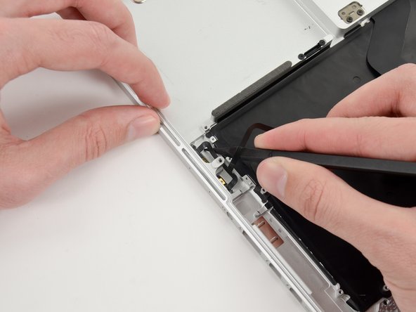
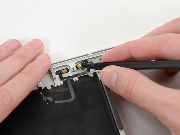
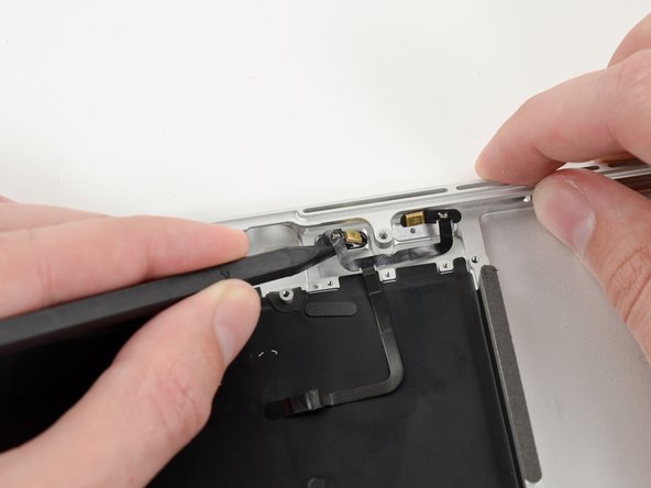
    • For this step, it is recommended to use a heat gun or hair dryer to soften the adhesive securing the microphone assembly to the upper case. You may be able to remove it without doing so, but will risk damaging the microphone cable.

    • With the heat gun set to low, heat the microphone assembly to loosen the adhesive attaching it to the upper case.

    • Be very careful not to overheat the microphones or upper case. Keep in mind that the plastic keyboard is on the other side—too much heat in a single place can melt keys.

  64. 这个步骤还没有翻译 帮忙翻译一下

    : 步骤 64 中的图像 1,3 : 步骤 64 中的图像 2,3 : 步骤 64 中的图像 3,3
    • Use the tip of a spudger to remove the piece of tape covering one of two microphones.

    • Grasp the piece of tape with a pair of tweezers and remove it.

  65. 这个步骤还没有翻译 帮忙翻译一下

    : 步骤 65 中的图像 1,3 : 步骤 65 中的图像 2,3 : 步骤 65 中的图像 3,3
    • Repeat the same procedure as the previous step to remove the tape covering the second microphone.

  66. 这个步骤还没有翻译 帮忙翻译一下

    : 步骤 66 中的图像 1,3 : 步骤 66 中的图像 2,3 : 步骤 66 中的图像 3,3
    • Wedge the tip of a spudger underneath the microphone assembly cable.

    • Run the spudger up along the bottom of the microphone assembly cable to separate it from the upper case.

  67. 这个步骤还没有翻译 帮忙翻译一下

    : 步骤 67 中的图像 1,2 : 步骤 67 中的图像 2,2
    • Gently wedge the tip of a spudger underneath the second microphone and push inwards to loosen the adhesive.

    • At this point the second microphone should be completely detached from the upper case.

  68. 这个步骤还没有翻译 帮忙翻译一下

    : 步骤 68 中的图像 1,2 : 步骤 68 中的图像 2,2
    • Carefully pry the first microphone up off the upper case.

  69. 这个步骤还没有翻译 帮忙翻译一下

    : 步骤 69 中的图像 1,1
    • Lift and remove the microphone assembly out of the upper case.

  70. 这个步骤还没有翻译 帮忙翻译一下

    : 步骤 70 中的图像 1,1
    • Upper case remains.

终点

14等其他人完成本指南。

2条评论

Wow, it worked! I am computer literate but have not taken my computer apart in years. Your photos and attention to detail were much appreciated. Any woman can and should attempt to do this herself. Thanks so much for the great tutorial!

Tricia

Patricia - 回复

If uppercase Assembly(Includes Trackpad, keyboard, Palmrest & BATTERY) is being replaced, there is no need to remove battery from old uppercase assembly.

Macrepair SF - 回复

添加评论

浏览统计数据:

过去 24 小时: 2

过去 7 天: 17

过去 30 天: 61

总计 20,692