跳转到主内容

当前版本的文档还未经巡查,您可以查看最新的已查核版本

你所需要的

  1. , 底壳: 步骤 1 中的图像 1,1
    在这个步骤中使用的工具:
    P5 Pentalobe Screwdriver Retina MacBook Pro and Air
    $5.99
    购买
    • 在开始更换之前,关机,合上屏幕然后把机器正面朝上平放在软面上。

    • 使用P5 Pentalobe 螺丝刀将底部的十颗螺丝移除,有下面两种规格:

    • 两个9mm 梅花形螺丝

    • 八个2.6mm梅花形螺丝

  2. : 步骤 2 中的图像 1,1
    • 把手指插进显示器和底壳之间的缝隙然后向上拉,即可拆下底壳。

    • 请小心地取下底壳并放在保证安全的地方。

  3. 这个步骤还没有翻译 帮忙翻译一下

    : 步骤 3 中的图像 1,2 : 步骤 3 中的图像 2,2
    • As a precaution against accidental discharge or shock, disconnect the battery connector from the logic board.

    • Grab the clear plastic pull tab attached to the battery connector and pull it toward the front edge of the Air to disconnect the battery from the logic board.

    • Be sure to pull the connector horizontally toward the battery, and not straight up from the Air, or you may damage the socket on the logic board.

  4. 这个步骤还没有翻译 帮忙翻译一下

    : 步骤 4 中的图像 1,1
    • Use the flat end of a spudger to pry the I/O board cable connector upward out of its socket on the I/O board.

  5. 这个步骤还没有翻译 帮忙翻译一下

    : 步骤 5 中的图像 1,1
    • Carefully peel the I/O board cable from the top of the fan.

  6. 这个步骤还没有翻译 帮忙翻译一下

    : 步骤 6 中的图像 1,2 : 步骤 6 中的图像 2,2
    • The following connector has an especially deep socket. Use care when disconnecting it.

    • While gently pulling the I/O board cable upward near its connection to the logic board, use the tip of a spudger to pry upward on alternating sides of the connector to help "walk" it out of its socket.

    • Remove the I/O board cable.

  7. 这个步骤还没有翻译 帮忙翻译一下

    : 步骤 7 中的图像 1,1
    • Use the tip of a spudger to carefully flip up the retaining flap on the fan cable ZIF socket.

    • Be sure you are prying up on the hinged retaining flap, not the socket itself.

  8. 这个步骤还没有翻译 帮忙翻译一下

    : 步骤 8 中的图像 1,1
    • Peel the rubber gasket off the adhesive on the top of the fan.

  9. 这个步骤还没有翻译 帮忙翻译一下

    : 步骤 9 中的图像 1,1
    • Remove the following three screws securing the fan to the upper case:

    • One 3.6 mm T5 Torx screw

    • One 2.7 mm T5 Torx screw

    • One 3.6 mm T5 Torx screw with a short head

  10. 这个步骤还没有翻译 帮忙翻译一下

    : 步骤 10 中的图像 1,1
    • Lift the fan out of the upper case and carefully pull the fan ribbon cable out of its socket as you remove it from the Air.

  11. 这个步骤还没有翻译 帮忙翻译一下

    : 步骤 11 中的图像 1,1
    • Disconnect the I/O board by pulling the power cable away from its socket on the logic board.

    • Pull the cable parallel to the face of the logic board toward the right edge of the Air.

  12. 这个步骤还没有翻译 帮忙翻译一下

    : 步骤 12 中的图像 1,1
    • Pull the camera cable parallel to the face of the I/O board toward the hinge of the Air to disconnect it from its socket, using the tip of a spudger to help push the connector out of its socket.

    • Do not lift upward on this cable as you disconnect it, as its socket may break off the logic board.

  13. 这个步骤还没有翻译 帮忙翻译一下

    : 步骤 13 中的图像 1,1
    • Use the flat end of a spudger to pry the left speaker cable connector up and out of its socket on the I/O board.

    • Pry up from beneath the wires.

  14. 这个步骤还没有翻译 帮忙翻译一下

    : 步骤 14 中的图像 1,2 : 步骤 14 中的图像 2,2
    • Use the tip of a spudger to flip up the retaining flap securing the microphone ribbon cable to the I/O board.

    • Use the tip of a spudger to remove the volume button ribbon cable from its ZIF connector on the I/O board.

  15. 这个步骤还没有翻译 帮忙翻译一下

    : 步骤 15 中的图像 1,1
    • Remove the single 4.0 mm T5 Torx screw securing the I/O board to the upper case.

  16. 这个步骤还没有翻译 帮忙翻译一下

    : 步骤 16 中的图像 1,1
    • Carefully lift the I/O board from its edge nearest the logic board and remove it from the upper case.

  17. 这个步骤还没有翻译 帮忙翻译一下

    : 步骤 17 中的图像 1,1
    • Remove the following five screws securing the battery to the upper case:

    • Three 6.3 mm T5 Torx screws

    • Two 2.4 mm T5 Torx screws

  18. 这个步骤还没有翻译 帮忙翻译一下

    : 步骤 18 中的图像 1,1
    • When handling the battery, avoid squeezing or touching the four exposed lithium polymer cells.

    • Lift the battery from its edge nearest the logic board and remove it from the upper case.

  19. 这个步骤还没有翻译 帮忙翻译一下

    : 步骤 19 中的图像 1,2 : 步骤 19 中的图像 2,2
    • Use the tip of a spudger or your fingernail to flip up the retaining flap on the trackpad ribbon cable ZIF socket.

    • Be sure you are prying up on the hinged retaining flap, not the socket itself.

    • Pull the trackpad ribbon cable straight out of its socket toward the front edge of the Air.

  20. 这个步骤还没有翻译 帮忙翻译一下

    : 步骤 20 中的图像 1,2 : 步骤 20 中的图像 2,2
    • Use the tip of a spudger to flip up the retaining flap on the keyboard backlight ribbon cable ZIF socket.

    • Be sure you are prying up on the hinged retaining flap, not the socket itself.

    • Use your spudger to help pull the cable out of its socket.

  21. 这个步骤还没有翻译 帮忙翻译一下

    : 步骤 21 中的图像 1,1
    • Use the flat end of a spudger to pry the right speaker cable connector up and out of its socket on the logic board.

    • Pry up from beneath the cables.

  22. 这个步骤还没有翻译 帮忙翻译一下

    : 步骤 22 中的图像 1,3 : 步骤 22 中的图像 2,3 : 步骤 22 中的图像 3,3
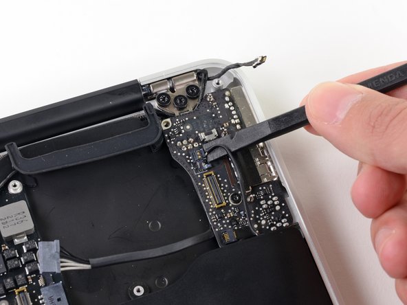
    • Gently push the tip of a spudger under the black plastic flap stuck to the display data cable lock to make the lock pop upward and away from the socket.

    • While holding the lock away from the socket, use the tip of a spudger and your fingers to gently remove the display data cable from its socket.

    • Do not pull upward on the display data cable as you disconnect it, as its socket may break off the logic board.

  23. 这个步骤还没有翻译 帮忙翻译一下

    : 步骤 23 中的图像 1,2 : 步骤 23 中的图像 2,2
    • Use the flat end of a spudger to pry both antenna cable connectors up and off their sockets on the AirPort/Bluetooth card.

  24. 这个步骤还没有翻译 帮忙翻译一下

    : 步骤 24 中的图像 1,1
    • Gently de-route the antenna cables from the slot cut into the logic board.

  25. 这个步骤还没有翻译 帮忙翻译一下

    : 步骤 25 中的图像 1,1
    • Remove the single 2.85 mm T5 Torx screw securing the SSD to the logic board.

  26. 这个步骤还没有翻译 帮忙翻译一下

    : 步骤 26 中的图像 1,2 : 步骤 26 中的图像 2,2
    • To avoid damaging its socket, do not lift the end of the SSD excessively.

    • Pull the drive straight out of its socket and remove it from the logic board.

    • When reinstalling the SSD, be sure it is properly seated before reinstalling its retaining screw.

  27. 这个步骤还没有翻译 帮忙翻译一下

    : 步骤 27 中的图像 1,1
    • Remove the six 6.3 mm T5 Torx screws securing the logic board to the upper case.

  28. 这个步骤还没有翻译 帮忙翻译一下

    : 步骤 28 中的图像 1,1
    • Remove the inner two 4.9 mm T8 Torx screws securing the antenna cable retainer and left clutch hinge to the upper case.

  29. 这个步骤还没有翻译 帮忙翻译一下

    : 步骤 29 中的图像 1,1
    • Push the antenna cable retainer away slightly and remove the 3 mm T5 Torx screw securing the end of the heat sink to the upper case.

  30. 这个步骤还没有翻译 帮忙翻译一下

    : 步骤 30 中的图像 1,1
    • Carefully remove the logic board assembly from the upper case, minding any cables that may get caught.

    • Hold the antenna cables out of the way as you lift the heat sink end of the logic board out of the upper case.

  31. 这个步骤还没有翻译 帮忙翻译一下

    : 步骤 31 中的图像 1,1
    • Remove the single 2.9 mm T5 Torx screw securing the AirPort/Bluetooth card to the logic board.

  32. 这个步骤还没有翻译 帮忙翻译一下

    : 步骤 32 中的图像 1,2 : 步骤 32 中的图像 2,2
    • Slightly lift the free end of the AirPort/Bluetooth board and pull it out of its socket on the logic board.

    • Remove the AirPort/Bluetooth board from the logic board.

  33. 这个步骤还没有翻译 帮忙翻译一下

    : 步骤 33 中的图像 1,1
    • Remove the four 2.5 mm T5 Torx screws securing the heat sink to the logic board.

  34. 这个步骤还没有翻译 帮忙翻译一下

    : 步骤 34 中的图像 1,1
    • If the heat sink seems to be stuck to the logic board after removing all four screws, use a spudger to carefully separate the heat sink from the faces of the CPU and GPU.

    • Remove the heat sink from the logic board.

    • When reinstalling the heat sink, be sure to apply a new layer of thermal paste. If you have never applied thermal paste before, we have a guide that makes it easy.

  35. 这个步骤还没有翻译 帮忙翻译一下

    : 步骤 35 中的图像 1,2 : 步骤 35 中的图像 2,2
    • Logic board remains.

    • When reassembling your logic board, be sure the rubber gasket is installed correctly. The nub on the gasket should mate with the hole cut into the logic board near the heat sink fins.

    • The rubber gasket should attach to the end of the heat sink as seen in the second picture.

终点

52等其他人完成本指南。

团队

iFixit iFixit 的会员

Staff

135 名成员

创作了16,722篇指南

9条评论

Those connections are scary small! The speaker connections in particular are very fragile and hard to get under to lift off. One of mine came apart, but it could be reassembled by first placing the plastic connector in the socket and carefully connecting the metal terminations into it. Be careful to orient the slot in the wire termination so it is vertical to interface with the lug in the socket, if that happens to you.

I had the dreaded "3 beep" (memory failure) problem and ordered a new logic board. Only when I had the old board out did I realize there was a compatibility problem- different board versions, connectors did not match. Since I was stuck anyway, I baked my old board in the oven (325 for 10 minutes) and reassembled it all so I would not lose any parts. I was surprised to have it boot up with the old (baked) board!

feraltech - 回复

I hate these lazy Haynes Manual type of articles that just tear down a product and give zero insight to the actual assembly. It's the type of knowledge that is just enough to be dangerous. Countless of times I've encountered that assembly IS NOT reverse of disassembly, where a specific tool or technique is required that is not covered in this lazy style of articles.

9 times out of 10, disassembly is the easy part and assembly the hard part.

vince chase - 回复

I did not find that to be an issue with this guide, reassembly was quite easy and was just the reverse of assembly. The whole thing took by less than 90 minutes beginning to end.

Mike Dacre - 回复

I feel that almost all assembly steps don't need repeating( a follow up reassemble step). In my opinion, assemble/reassemble steps involving a ribbon/flex cable and ZIF socket would be helpful, especially for newbies. Thats just one techs opinion. All that said, I feel the author did a fantastic job and I had no trouble removing/reinstalling my logic board and components. Thank you A. Goldberg and keep up the good work.

Pete - 回复

Great guide! I wish I had found this before I followed the ‘tear down’ guide; hopefully I didn’t break anything doing it that way. The I/O board camera connector was the worst — it really requires quite a pull to release. It would be ideal to have a close-up showing exactly where to put the spudger tip to push. Also, the speakers were rather well glued down, but eventually did release. Pointing out where the glue point is (in the notch just before the bend on the right=hand one) would have helped me.

richshop2 - 回复

添加评论

浏览统计数据:

过去 24 小时: 2

过去 7 天: 25

过去 30 天: 156

总计 63,241