For precautionary purposes, we advise that you disconnect the battery connector from the logic board to avoid any electrical discharge. This step is optional and is not required.
Grab the clear plastic pull tab attached to the battery connector and pull it toward the front edge of the Air to disconnect the battery from the logic board.
Do not lift upward on the connector as you disconnect it.
The following connector has an especially deep socket. Use care when disconnecting it.
Carefully peel the I/O board cable from the top of the fan.
While gently pulling the I/O board cable upward near its connection to the logic board, use the tip of a spudger to pry upward on alternating sides of the connector to help "walk" it out of its socket.
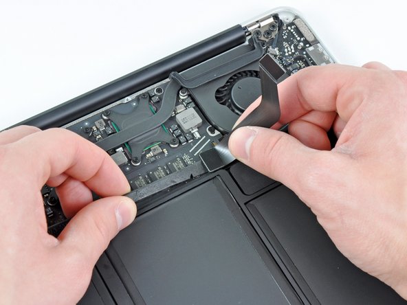
Pull the camera cable parallel to the face of the I/O board toward the corner of the Air to disconnect it from its socket, using the tip of a spudger to help push the connector out of its socket.
Do not lift upward on this cable as you disconnect it, as its socket may break off the logic board.
Gently push the tip of a spudger under the black plastic flap stuck to the display data cable lock to make the lock pop upward and away from the socket.
While holding the lock away from the socket, use the tip of a spudger and your fingers to gently remove the display data cable from its socket by sliding it toward the corner of the Air.
Do not pull upward on the display data cable as you disconnect it, as its socket may break off the logic board.
Before removing the last display screw, be sure to hold the display and upper case steady with your other hand. Failure to do so may allow the components to fall onto the table, causing potentially expensive damage.
Remove the last 4.9 mm T8 Torx screw securing the display to the upper case.
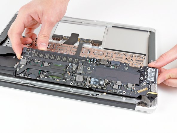
Push the upper case slightly toward the display assembly, then rotate it away from the front of the display assembly.
Once the two display hinges have cleared the upper case, remove the display and set it aside.
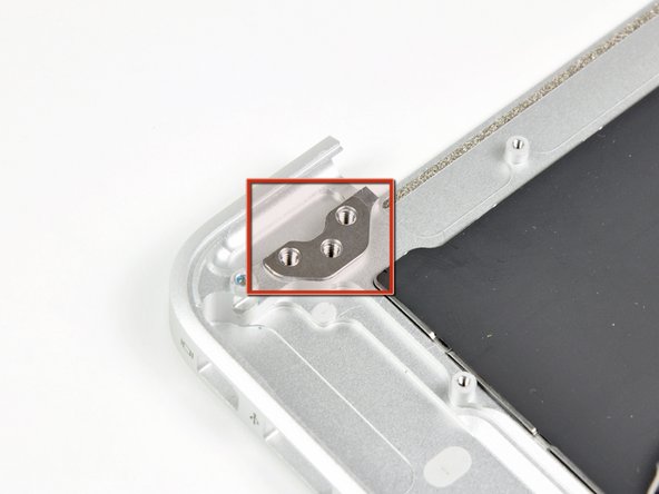
Keep track of the shims under each of the two display brackets. When installing the display, be sure a shim is installed under each display bracket (against the upper case) as shown in the second picture.
Removing the logic board is completely unnecessary and you risk damaging more components. Follow steps 1-3, 11, 20-22, 26, 30-34. Obviously be careful not to damage the board when you are actually taking the display off.
Excellent guide, however, I would like to note that removing the logic board is completely unnecessary. In the process of doing so, I ended up breaking my right speaker socket from the logic board. The simpler method is to just unscrew the display hinge, antenna, and isight cable, then remove and replace display.