当前版本的文档还未经巡查,您可以查看最新的已查核版本 。
在这个步骤中使用的工具:
P5 Pentalobe Screwdriver Retina MacBook Pro and Air
$5.99
购买
In this step you will disconnect the battery to help avoid shorting out any components during service.
Use the flat end of a spudger to pry both short sides of the battery connector upward to disconnect it from its socket on the logic board.
Bend the battery cable slightly away from the logic board so the connector will not accidentally bend back and make contact with its socket.
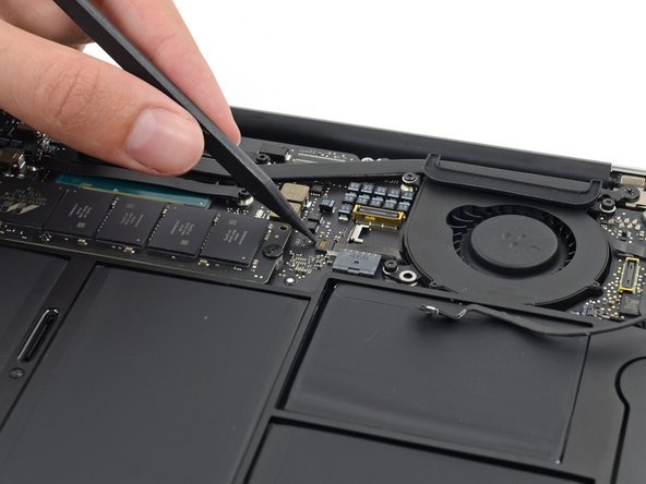
Use the tip of a spudger to carefully push on each side of the iSight camera cable connector to loosen it out of its socket on the logic board.
We recommend you gently "walk" the connector out of its socket.
Use the tip of a spudger to carefully flip up the retaining flap on the fan cable ZIF socket.
Be sure you are prying up on the hinged retaining flap, not the socket itself.
Remove the following three screws securing the fan to the upper case:
Two 5.5 mm T5 Torx screws
One 4.6 mm T5 Torx screw
In some models this is a 3.6 mm T5 Torx screw.
Lift, but do not remove the fan out of its recess in the upper case.
Carefully pull the fan ribbon cable out of its socket as you remove the fan from the Air.
Remove the following five screws securing the battery to the upper case:
Two 5.2 mm T5 Torx screws
One 6 mm T5 Torx screw
Two 2.6 mm T5 Torx screws
When handling the battery, avoid squeezing or touching the six exposed lithium polymer cells.
Lift the battery from its edge nearest the logic board and remove it from the upper case.
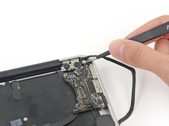
Gently push the tip of a spudger under the black plastic flap stuck to the display data cable lock to make the lock pop upward and away from the socket.
While holding the lock away from the socket, gently pull the display data cable out of its socket.
Do not pull upward on the display data cable as you disconnect it, as its socket may break off the logic board.
Use the tip of a spudger to pry under the speaker cable connector, lifting it straight up from its socket.
De-route the cable from its notch in the logic board.
Use the tip of a spudger or your fingernail to flip up the retaining flap on the trackpad ribbon cable ZIF socket.
Be sure you are prying up on the hinged retaining flap, not the socket itself.
Pull the trackpad ribbon cable straight out of its socket toward the front edge of the Air.
Use the tip of a spudger to flip up the retaining flap on the keyboard backlight ribbon cable ZIF socket.
Be sure you are prying up on the hinged retaining flap, not the socket itself.
Pull the keyboard backlight ribbon cable out of its socket.
Slightly lift the free end of the AirPort/Bluetooth board and pull it out of its socket on the logic board.
To avoid damaging its socket on the logic board, do not excessively lift the free end of the AirPort/Bluetooth card.
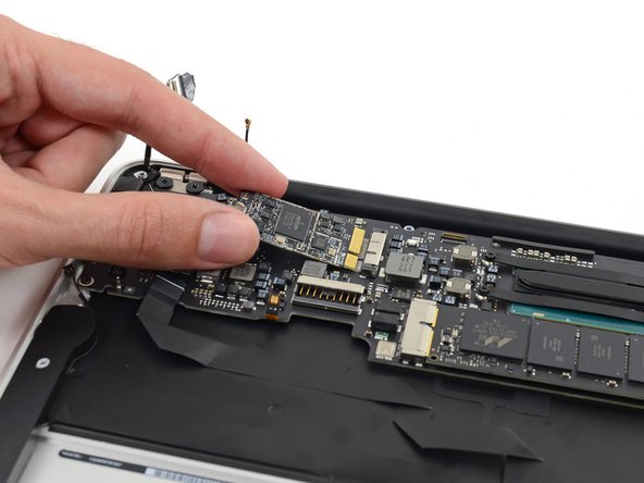
Gently lift the logic board assembly from the heat sink end and pull it away from the port side of the case to remove it from the Air.
When replacing the logic board, insert the board's rubber edge under the port-side rubber gasket, then lower the board into place.
Use the tip of a spudger to carefully flip up the retaining flap on the microphone cable ZIF socket.
Be sure you are prying up on the retaining flap, not the socket itself.
With a pair of tweezers, pull the microphone ribbon cable straight out of its socket.
Use the tip of a spudger to pry under the speaker cable near the connector, lifting it straight up from its socket.
De-route the cable from its notch in the logic board.
Peel up the six cable loops securing the antenna cables to the upper case.
In some models there are seven cable loops.
Gently pull the cable loops slightly out of the channel cut into the upper case one at a time.
Use your spudger to open up the plastic loops as you de-route the antenna cables through them.
Repeat this for each retaining loop until the antenna cables are free from the upper case.
Open the display until it is perpendicular to the upper case and place it on a table as shown.
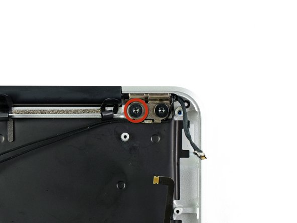
While holding the Air steady, remove the remaining 4.9 mm T8 Torx screw from the lower display bracket.
Before removing the last display screw, be sure to hold the display and upper case steady with your other hand. Failure to do so may allow the components to fall onto the table, causing potentially expensive damage.
Remove the last 4.9 mm T8 Torx screw securing the display to the upper case.
Push the upper case slightly toward the display assembly, then rotate it away from the front of the display assembly.
Once the two display hinges have cleared the upper case, remove the display.
嵌入本指南
选择一个尺寸并复制下面的代码,将本指南作为一个小插件嵌入到你的网站/论坛中。
单个步骤
完整指南
小——600像素
中——800像素
大——1200像素
预览