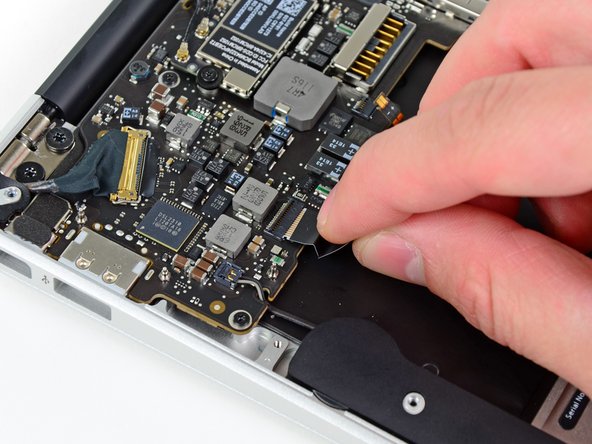
Use the flat end of a spudger to lift the I/O board connector up and out of its socket on the logic board
Be sure to lift straight up on the connector as you disconnect it from its socket. The socket is very deep on the logic board and prying it from side to side may damage the logic board
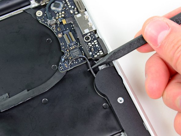
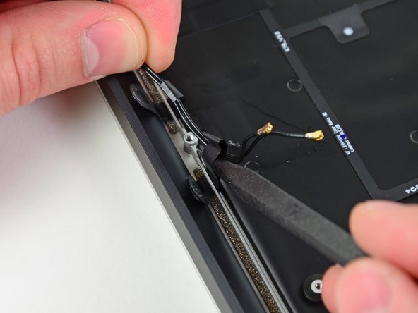
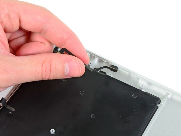
Gently push the tip of a spudger under the black plastic flap stuck to the display data cable lock to make the lock pop upward and away from the socket.
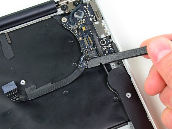
Remove the small rubber gasket from the corner of the upper case near the display data cable.
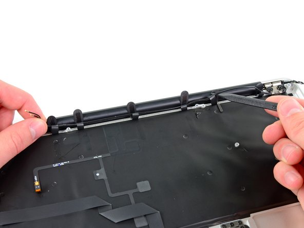
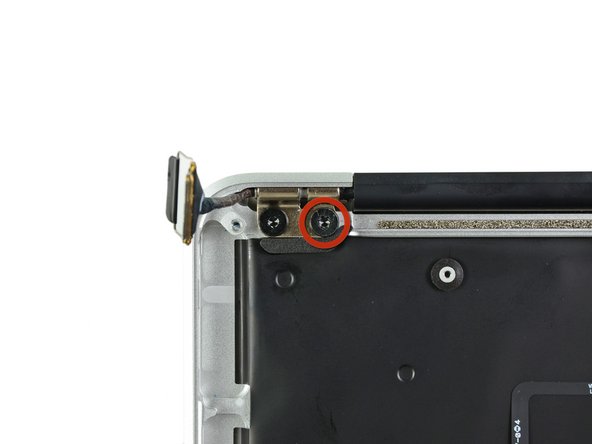
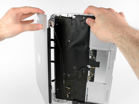
Before removing the last display screw, be sure to hold the display and upper case steady with your other hand. Failure to do so may allow the components to fall onto the table, causing potentially expensive damage.
Remove the last 4.9 mm T8 Torx screw securing the display to the upper case.
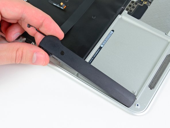
Use the flat end of a spudger to pry the right speaker off the adhesive securing it to the upper case.
Only pry up on the speaker from the areas of bare aluminum on the upper case. Prying up from the keyboard area may damage the keyboard and the speaker itself.
Use the flat end of a spudger to pry the left speaker off the adhesive securing it to the upper case.
Only pry up on the speaker from the areas of bare aluminum on the upper case. Prying up from the keyboard area may damage the keyboard and the speaker itself.