跳转到主内容

当前版本的文档还未经巡查,您可以查看最新的已查核版本

你所需要的

  1. , 底壳: 步骤 1 中的图像 1,1
    在这个步骤中使用的工具:
    P5 Pentalobe Screwdriver Retina MacBook Pro and Air
    $5.99
    购买
    • 电脑关机,并将其合上。 将电脑倒置并放置在柔软的表面上。

    • 移除下列十颗螺丝:

    • 2颗 8mm 5点防撬螺丝。

    • 8颗 2.5mm 5点防撬螺丝。

    • 这里需要使用特制的螺丝刀来移除5点防撬螺丝-可以在这里找到特制螺丝刀

  2. : 步骤 2 中的图像 1,1
    • 在显示屏和下壳之间插入手指,向上拉,将底壳从Air中弹出。

  3. , 电池: 步骤 3 中的图像 1,2 , 电池: 步骤 3 中的图像 2,2
    • 在此步驟中,建议断开电池电源,以避免在维修期间短路任何组件。

    • 使用撬棒的平头将电池连接器的两个短边向上撬开,使其与逻辑板上的插座断开连接。

    • 将电池电线远离逻辑板,使连接器不会意外接触插座。

  4. 这个步骤还没有翻译 帮忙翻译一下

    : 步骤 4 中的图像 1,1
    • Remove the single 2.9 mm T5 Torx screw securing the SSD to the logic board.

  5. 这个步骤还没有翻译 帮忙翻译一下

    : 步骤 5 中的图像 1,2 : 步骤 5 中的图像 2,2
    • Use a spudger to help lift the free end of the SSD just enough to grab it with your other hand.

    • Do not lift the end of the SSD excessively.

    • Pull the drive straight out of its socket and remove it from the logic board.

    • When reinstalling the SSD, be sure it is properly seated before reinstalling its retaining screw.

  6. 这个步骤还没有翻译 帮忙翻译一下

    : 步骤 6 中的图像 1,1
    • Use the flat end of a spudger to pry the I/O board cable up from its socket on the I/O board.

  7. 这个步骤还没有翻译 帮忙翻译一下

    : 步骤 7 中的图像 1,1
    • Peel the I/O board cable up from the adhesive securing it to the fan.

  8. 这个步骤还没有翻译 帮忙翻译一下

    : 步骤 8 中的图像 1,2 : 步骤 8 中的图像 2,2
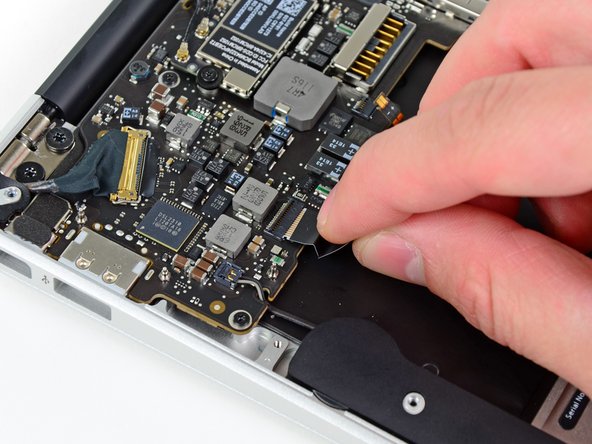
    • Use the flat end of a spudger to lift the I/O board connector up and out of its socket on the logic board

    • Be sure to lift straight up on the connector as you disconnect it from its socket. The socket is very deep on the logic board and prying it from side to side may damage the logic board

    • Remove the I/O board cable.

  9. 这个步骤还没有翻译 帮忙翻译一下

    : 步骤 9 中的图像 1,1
    • Use the tip of a spudger to carefully flip up the retaining flap on the fan cable ZIF socket.

    • Be sure you are prying up on the hinged retaining flap, not the socket itself.

  10. 这个步骤还没有翻译 帮忙翻译一下

    : 步骤 10 中的图像 1,1
    • Remove the following three screws securing the fan to the upper case:

    • Two 5.2 mm T5 Torx screws

    • One 3.6 mm T5 Torx screw

  11. 这个步骤还没有翻译 帮忙翻译一下

    : 步骤 11 中的图像 1,1
    • Lift the fan out of the upper case and carefully pull the fan ribbon cable out of its socket as you remove it from the Air.

  12. 这个步骤还没有翻译 帮忙翻译一下

    : 步骤 12 中的图像 1,1
    • Remove the following five screws securing the battery to the upper case:

    • Two 5.2 mm T5 Torx screws

    • One 6 mm T5 Torx screw

    • Two 2.6 mm T5 Torx screws

  13. 这个步骤还没有翻译 帮忙翻译一下

    : 步骤 13 中的图像 1,1
    • Do not touch or squeeze the six lithium polymer cells when handling the battery.

    • Lift the battery from its edge nearest the logic board and remove it from the upper case.

  14. 这个步骤还没有翻译 帮忙翻译一下

    : 步骤 14 中的图像 1,2 : 步骤 14 中的图像 2,2
    • Use the flat end of a spudger to free the adhesive loop securing the I/O board power cable to the upper case.

    • Disconnect the I/O board by pulling the power cable away from its socket on the logic board.

    • Pull the cable parallel to the face of the logic board toward the front edge of the Air.

  15. 这个步骤还没有翻译 帮忙翻译一下

    : 步骤 15 中的图像 1,2 : 步骤 15 中的图像 2,2
    • Use the tip of a spudger to flip up the retaining flap on the keyboard backlight ribbon cable ZIF socket.

    • Be sure you are prying up on the hinged retaining flap, not the socket itself.

    • Pull the keyboard backlight ribbon cable out of its socket.

  16. 这个步骤还没有翻译 帮忙翻译一下

    : 步骤 16 中的图像 1,2 : 步骤 16 中的图像 2,2
    • Use the tip of a spudger or your fingernail to flip up the retaining flap on the trackpad ribbon cable ZIF socket.

    • Be sure you are prying up on the hinged retaining flap, not the socket itself.

    • Pull the trackpad ribbon cable straight out of its socket toward the front edge of the Air.

  17. 这个步骤还没有翻译 帮忙翻译一下

    : 步骤 17 中的图像 1,1
    • Use the tip of a spudger to de-route the right speaker cable from the slot cut into the logic board.

  18. 这个步骤还没有翻译 帮忙翻译一下

    : 步骤 18 中的图像 1,1
    • Use the flat end of a spudger to pry the right speaker cable connector up and out of its socket on the logic board.

    • Pry up from beneath the cables.

  19. 这个步骤还没有翻译 帮忙翻译一下

    : 步骤 19 中的图像 1,3 : 步骤 19 中的图像 2,3 : 步骤 19 中的图像 3,3
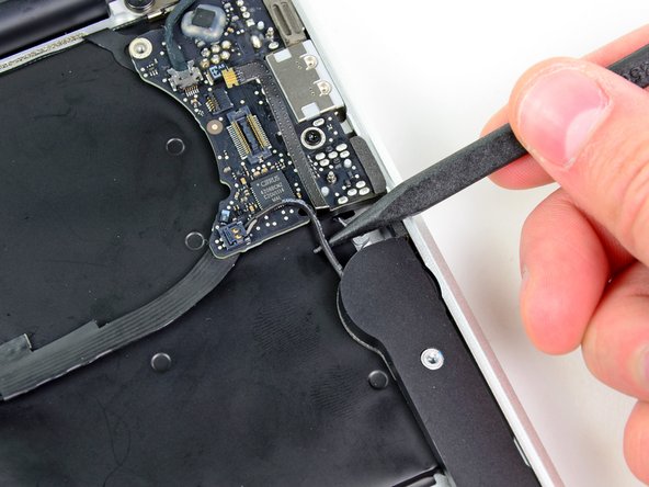
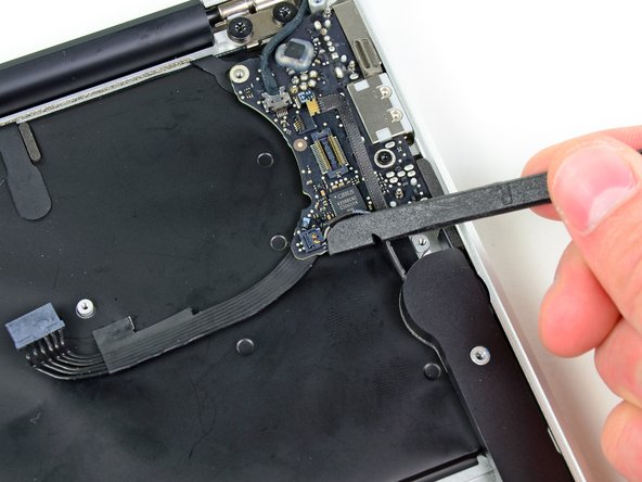
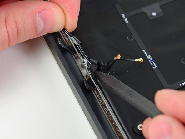
    • Gently push the tip of a spudger under the black plastic flap stuck to the display data cable lock to make the lock pop upward and away from the socket.

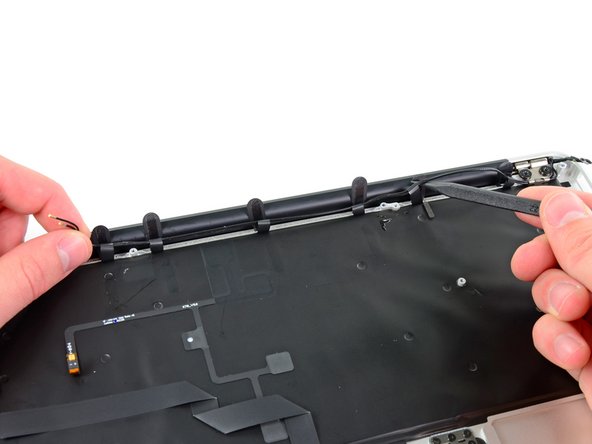
    • Remove the small rubber gasket from the corner of the upper case near the display data cable.

  20. 这个步骤还没有翻译 帮忙翻译一下

    : 步骤 20 中的图像 1,1
    • While holding the lock away from the socket, gently pull the display data cable out of its socket.

    • Do not pull upward on the display data cable as you disconnect it, as its socket may break off the logic board.

  21. 这个步骤还没有翻译 帮忙翻译一下

    : 步骤 21 中的图像 1,2 : 步骤 21 中的图像 2,2
    • Use the flat end of a spudger to pry both antenna cable connectors up and off their sockets on the AirPort/Bluetooth card.

  22. 这个步骤还没有翻译 帮忙翻译一下

    : 步骤 22 中的图像 1,1
    • Gently de-route the antenna cables from the slot cut into the logic board.

  23. 这个步骤还没有翻译 帮忙翻译一下

    : 步骤 23 中的图像 1,1
    • Remove the three 3.6 mm T5 Torx screws securing the logic board to the upper case.

  24. 这个步骤还没有翻译 帮忙翻译一下

    : 步骤 24 中的图像 1,1
    • Gently lift the logic board assembly out of the upper case, minding the fragile heat sink and any cables that may get caught.

  25. 这个步骤还没有翻译 帮忙翻译一下

    : 步骤 25 中的图像 1,1
    • Remove the small rubber gasket from the corner of the upper case nearest the I/O board.

  26. 这个步骤还没有翻译 帮忙翻译一下

    : 步骤 26 中的图像 1,2 : 步骤 26 中的图像 2,2
    • Use the tip of a spudger to carefully flip up the retaining flap on the microphone cable ZIF socket.

    • Be sure you are prying up on the retaining flap, not the socket itself.

    • Pull the microphone ribbon cable straight out of its socket.

  27. 这个步骤还没有翻译 帮忙翻译一下

    : 步骤 27 中的图像 1,2 : 步骤 27 中的图像 2,2
    • De-route the left speaker cable from the notch cut into the I/O board.

    • Use the flat end of a spudger to pry the left speaker cable connector up and out of its socket on the I/O board.

    • Pry up from beneath the wires.

  28. 这个步骤还没有翻译 帮忙翻译一下

    : 步骤 28 中的图像 1,1
    • Pull the camera cable parallel to the face of the I/O board toward the rear edge of the Air to disconnect it from its socket.

    • Do not lift upward on this cable as you disconnect it, as its socket may break off the logic board.

  29. 这个步骤还没有翻译 帮忙翻译一下

    : 步骤 29 中的图像 1,1
    • Remove the single 3.6 mm T5 Torx screw securing the I/O board to the upper case.

  30. 这个步骤还没有翻译 帮忙翻译一下

    : 步骤 30 中的图像 1,1
    • Carefully lift the I/O board from its edge nearest the logic board and remove it from the upper case.

  31. 这个步骤还没有翻译 帮忙翻译一下

    : 步骤 31 中的图像 1,3 : 步骤 31 中的图像 2,3 : 步骤 31 中的图像 3,3
    • Peel up the six cable loops securing the antenna cables to the upper case.

    • Gently pull the cable loops slightly out of the channel cut into the upper case one at a time.

    • Use your spudger to open up the plastic loops as you de-route the antenna cables through them.

    • Repeat this for all of the retaining loops.

  32. 这个步骤还没有翻译 帮忙翻译一下

    : 步骤 32 中的图像 1,2 : 步骤 32 中的图像 2,2
    • Remove the inner 4.9 mm T8 Torx screw securing each display hinge to the upper case (two screws total).

  33. 这个步骤还没有翻译 帮忙翻译一下

    : 步骤 33 中的图像 1,1
    • Open the display until it is perpendicular to the upper case and place it on a table as shown.

    • While holding the Air steady, remove the remaining 4.9 mm T8 Torx screw from the lower display bracket.

  34. 这个步骤还没有翻译 帮忙翻译一下

    : 步骤 34 中的图像 1,1
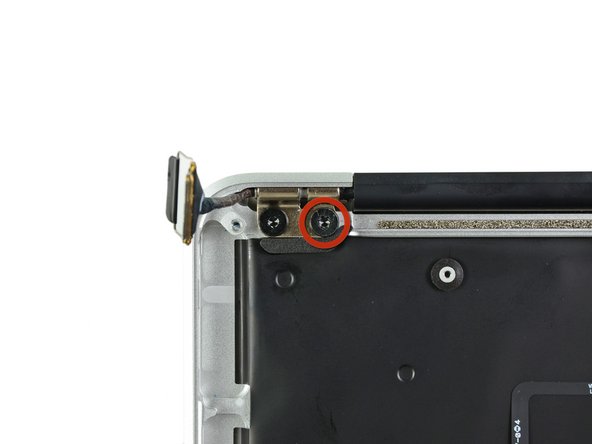
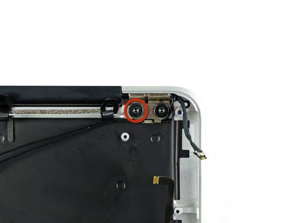
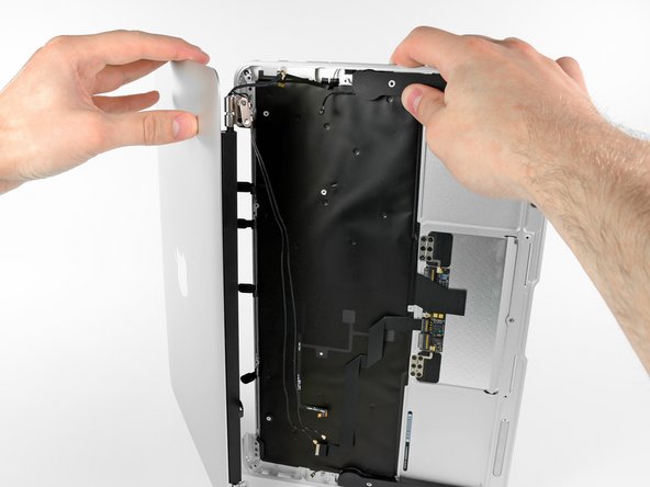
    • Before removing the last display screw, be sure to hold the display and upper case steady with your other hand. Failure to do so may allow the components to fall onto the table, causing potentially expensive damage.

    • Remove the last 4.9 mm T8 Torx screw securing the display to the upper case.

  35. 这个步骤还没有翻译 帮忙翻译一下

    : 步骤 35 中的图像 1,2 : 步骤 35 中的图像 2,2
    • Push the upper case slightly toward the display assembly, then rotate it away from the front of the display assembly.

    • Once the two display hinges have cleared the upper case, remove the display and set it aside.

终点

71等其他人完成本指南。

5条评论

Thanks a lot for this guide! My daughter wrecked the display on my Macbook Air. I have never done any repairs on a notebook before, but I ordered the new display assembly and the toolkit and went ahead anyways.

When I saw my Macbook Air in pieces before me, I had my doubts that it would ever work again, but placing the last screw and then pressing the power button, it just worked!

Thanks again!

kenneth - 回复

Because my MacBook Air late 2011 ‘s hinge was broken, I would like to replace a new one DIY! Thank for show me hoe to disassemble it.

bryan mok - 回复

Very helpful - thank you very much. I watched your Youtube video (for a slightly different model) to get an idea of the process, then followed this guide step-by-step for my exact model. Very clear and easy to follow, with great directions and pictures.

Maciek - 回复

Used this excellent and comprehensive guide for early 11” Air along side the video guide for the later 13” Macbook Air to swap out the display on a 2015 11” Macbook Air - All very similar and made a daunting job straight forward - Thanks!

N Fqwerty - 回复

Switched two monitors and made a great job thanks to this amzing guide. Very easy.

alessandro.vianello - 回复

添加评论

浏览统计数据:

过去 24 小时: 0

过去 7 天: 11

过去 30 天: 80

总计 67,894