跳转到主内容

当前版本的文档还未经巡查,您可以查看最新的已查核版本

你所需要的

  1. , 外壳: 步骤 1 中的图像 1,2 , 外壳: 步骤 1 中的图像 2,2
    • 拨动图中所示的闩子至右侧“unlocked”位置。

  2. : 步骤 2 中的图像 1,3 : 步骤 2 中的图像 2,3 : 步骤 2 中的图像 3,3
    • 向上垂直提起Mac pro外壳。

    • 提起外壳时,可以按着顶部的散热风扇。

  3. 这个步骤还没有翻译 帮忙翻译一下

    : 步骤 3 中的图像 1,3 : 步骤 3 中的图像 2,3 : 步骤 3 中的图像 3,3
    • Remove five 5.1 mm T10 Torx screws from around the outer perimeter of the fan assembly.

  4. 这个步骤还没有翻译 帮忙翻译一下

    : 步骤 4 中的图像 1,2 : 步骤 4 中的图像 2,2
    • The fan assembly is attached to the rest of the computer by two cables on the IO board side.

    • Tilt the assembly up away from the IO board.

    • Do not try to remove the fan assembly yet, as it is still attached by two cables.

  5. 这个步骤还没有翻译 帮忙翻译一下

    : 步骤 5 中的图像 1,1
    • While supporting the fan assembly with one hand, loosen the two T8 captive screws in the fan cable bracket.

    • These screws are captive in the Mac Pro. Do not try to remove these screws from your Mac Pro.

  6. 这个步骤还没有翻译 帮忙翻译一下

    : 步骤 6 中的图像 1,1
    • Use a pair of tweezers to pull the fan cable bracket away from the fan assembly.

  7. 这个步骤还没有翻译 帮忙翻译一下

    : 步骤 7 中的图像 1,2 : 步骤 7 中的图像 2,2
    • Use the flat end of a spudger to disconnect the fan assembly ribbon cable from the IO board.

  8. 这个步骤还没有翻译 帮忙翻译一下

    : 步骤 8 中的图像 1,1
    • Disconnect the fan assembly antenna cable from the IO board.

    • Remove the fan assembly from the Mac Pro.

  9. 这个步骤还没有翻译 帮忙翻译一下

    : 步骤 9 中的图像 1,3 : 步骤 9 中的图像 2,3 : 步骤 9 中的图像 3,3
    • Flip the Mac Pro upside down, 180 degrees.

    • Remove five 5.1 mm T10 Torx screws from the outer perimeter of the lower case.

  10. 这个步骤还没有翻译 帮忙翻译一下

    : 步骤 10 中的图像 1,2 : 步骤 10 中的图像 2,2
    • Carefully lift the lower case up and remove it from the Mac Pro.

  11. 这个步骤还没有翻译 帮忙翻译一下

    : 步骤 11 中的图像 1,2 : 步骤 11 中的图像 2,2
    • Use the flat end of a spudger and a twisting motion to gently separate one side of the graphics card data connection.

  12. 这个步骤还没有翻译 帮忙翻译一下

    : 步骤 12 中的图像 1,3 : 步骤 12 中的图像 2,3 : 步骤 12 中的图像 3,3
    • Gently separate the other side as well.

    • Flip the connector up and out of the way of the graphics card.

    • Repeat this procedure on the other graphics card.

  13. 这个步骤还没有翻译 帮忙翻译一下

    : 步骤 13 中的图像 1,1
    • Remove the two 6.0 mm T8 Torx screws securing the interconnect board to the heat sink.

  14. 这个步骤还没有翻译 帮忙翻译一下

    : 步骤 14 中的图像 1,3 : 步骤 14 中的图像 2,3 : 步骤 14 中的图像 3,3
    • Gently walk the interconnect board straight up off the logic board's slot connection.

    • It is recommended to lift one side and then the other.

    • Do not try to remove the interconnect board from the Mac Pro yet, as it is still connected to the IO board.

  15. 这个步骤还没有翻译 帮忙翻译一下

    : 步骤 15 中的图像 1,2 : 步骤 15 中的图像 2,2
    • Flip the interconnect board up and over, exposing the IO board data cable.

    • Use the same sort of twisting and spreading motion with the flat end of a spudger to separate one side of the IO board data cable.

  16. 这个步骤还没有翻译 帮忙翻译一下

    : 步骤 16 中的图像 1,2 : 步骤 16 中的图像 2,2
    • Use the flat end of a spudger to separate the other side of the IO board data cable.

    • Bend the cable out of the way and remove the interconnect board from the Mac Pro.

  17. 这个步骤还没有翻译 帮忙翻译一下

    : 步骤 17 中的图像 1,1
    • Flip the Mac Pro back over and set it gently on a flat surface.

    • We recommend laying the Mac Pro on the corner of the heat sink and the two standoff screw posts that attach to the interconnect board.

  18. 这个步骤还没有翻译 帮忙翻译一下

    : 步骤 18 中的图像 1,2 : 步骤 18 中的图像 2,2
    • Remove the two 3.6 mm T5 Torx screws from the sides of the power supply cage (one on each side).

  19. 这个步骤还没有翻译 帮忙翻译一下

    : 步骤 19 中的图像 1,1
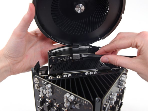
    • Remove the power supply cage from the top of the power supply.

    • By removing this cage, you are exposing internal components of the power supply. Be very careful not to touch any of the power supply components or circuitry.

    • Be careful not to drop any screws or tools into the power supply, as this may damage the power supply.

  20. 这个步骤还没有翻译 帮忙翻译一下

    : 步骤 20 中的图像 1,1
    • Remove the four 5.5 mm T8 Torx screws securing the power supply assembly to the Mac Pro.

  21. 这个步骤还没有翻译 帮忙翻译一下

    : 步骤 21 中的图像 1,1
    • Remove the power supply assembly from the Mac Pro.

  22. , 电源: 步骤 22 中的图像 1,3 , 电源: 步骤 22 中的图像 2,3 , 电源: 步骤 22 中的图像 3,3
    • 使用平尾的撬棒来断开直流输出接口,此接口位于IO板上的插槽中。

    • 从IO板上撬起电源数据线。

    • 请确保直接撬开j接口,而不是插座。对两根线缆都如此。

  23. : 步骤 23 中的图像 1,2 : 步骤 23 中的图像 2,2
    • 移除电源板边缘的4个9.00mm银制T10十字螺丝。

    • 电源在一定程度上悬垂在这些螺丝上,因此您需要将螺丝到固定在一定的角度上。

  24. 这个步骤还没有翻译 帮忙翻译一下

    : 步骤 24 中的图像 1,2 : 步骤 24 中的图像 2,2
    • Gently shift the power supply to free the AC power inlet cable out of its plastic clip.

    • Be careful not to try to separate the power supply from the IO board assembly just yet, as it is still connected by the AC power inlet cable.

  25. : 步骤 25 中的图像 1,2 : 步骤 25 中的图像 2,2
    • 将电源翻转到背面以露出交流电源线。

  26. : 步骤 26 中的图像 1,2 : 步骤 26 中的图像 2,2
    • 挤压交流电源线缆接口,将其拉出插槽。

  27. 这个步骤还没有翻译 帮忙翻译一下

    : 步骤 27 中的图像 1,1
    • Remove the two 9 mm silver T10 Torx screws securing the IO Board to the IO shield.

  28. 这个步骤还没有翻译 帮忙翻译一下

    : 步骤 28 中的图像 1,2 : 步骤 28 中的图像 2,2
    • Lift the IO board up from the IO shield from the end with the AC plug.

    • Do not attempt to completely separate the IO board from the IO shield, as there are still two cables connecting the two components.

  29. 这个步骤还没有翻译 帮忙翻译一下

    : 步骤 29 中的图像 1,3 : 步骤 29 中的图像 2,3 : 步骤 29 中的图像 3,3
    • Set the assembly down on a flat surface to access the connectors on the IO board.

    • Use the tip of a spudger to flip the retaining flap on the IO shield ribbon cable ZIF connector.

    • Disconnect the IO shield ribbon cable.

  30. 这个步骤还没有翻译 帮忙翻译一下

    : 步骤 30 中的图像 1,2 : 步骤 30 中的图像 2,2
    • Squeeze and pull the audio jack ribbon cable connector from the IO board.

终点

5等其他人完成本指南。

团队

iFixit iFixit 的会员

Staff

135 名成员

创作了16,731篇指南

3条评论

How do you even get the a t10 to fit a such an aggressive angle?

Clayton Voges - 回复

My USB ports don’t work.. I replaced this board and they still don’t work.. Suggestions as to what could be causing this?

Michael Warchut - 回复

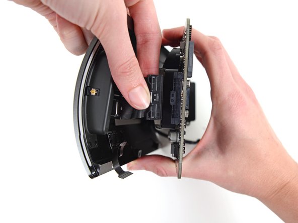
I’m having a severe problem with the data cable the runs from the power supply to the IO board. First, I broke a couple of the pins, so I had to order a new IO board. Now the pins are slightly different. Before, they were just sitting out unprotected, but the new board I purchased has a type of barrier around it, but my data cable won’t fit onto the pins now with the new protective barriers. Please help!

brian - 回复

添加评论

浏览统计数据:

过去 24 小时: 5

过去 7 天: 26

过去 30 天: 111

总计 7,872