跳转到主内容

Mac Mini Late 2014 Logic Board Assembly Replacement

仅作为前提条件
本指南仅用作其他指南的先决条件。不能单独食用。

你所需要的

  1. Mac Mini Late 2014 Logic Board Assembly Replacement, Logic Board Assembly: 步骤 1 中的图像 1,1
    • Remove the 2.6 mm T6 screw securing the SATA cable connector bracket.

  2. Mac Mini Late 2014 Logic Board Assembly Replacement: 步骤 2 中的图像 1,2 Mac Mini Late 2014 Logic Board Assembly Replacement: 步骤 2 中的图像 2,2
    • Remove the SATA cable connector bracket.

  3. Mac Mini Late 2014 Logic Board Assembly Replacement: 步骤 3 中的图像 1,2 Mac Mini Late 2014 Logic Board Assembly Replacement: 步骤 3 中的图像 2,2
    • Use the flat end of a spudger to lift the SATA cable connector up off of its socket on the logic board.

  4. Mac Mini Late 2014 Logic Board Assembly Replacement: 步骤 4 中的图像 1,2 Mac Mini Late 2014 Logic Board Assembly Replacement: 步骤 4 中的图像 2,2
    • Use the tip of a spudger to disconnect the IR sensor cable connector by prying it straight up from its socket.

  5. Mac Mini Late 2014 Logic Board Assembly Replacement: 步骤 5 中的图像 1,1
    • The following three steps only apply to Mac minis equipped with a PCIe SSD. Skip the next three steps if your Mac mini only has a hard drive.

    • Remove the two 2.6 mm T6 screws securing the PCIe SSD cable bracket.

  6. Mac Mini Late 2014 Logic Board Assembly Replacement: 步骤 6 中的图像 1,2 Mac Mini Late 2014 Logic Board Assembly Replacement: 步骤 6 中的图像 2,2
    • Remove the PCIe SSD cable bracket.

  7. Mac Mini Late 2014 Logic Board Assembly Replacement: 步骤 7 中的图像 1,2 Mac Mini Late 2014 Logic Board Assembly Replacement: 步骤 7 中的图像 2,2
    • Lift the PCIe SSD connector up off its socket.

  8. Mac Mini Late 2014 Logic Board Assembly Replacement: 步骤 8 中的图像 1,1
    • Remove the single 16 mm T6 screw securing the logic board.

  9. Mac Mini Late 2014 Logic Board Assembly Replacement: 步骤 9 中的图像 1,1
    在这个步骤中使用的工具:
    Mac mini Logic Board Removal Tool
    $4.99
    购买
    • To remove the logic board, the two cylindrical rods of the Mac mini Logic Board Removal Tool must be inserted into the holes highlighted in red. Inserting instruments into any logic board holes other than the ones highlighted in red may destroy the logic board.

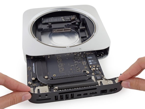
    • Insert the Mac mini Logic Board Removal Tool into the two holes highlighted in red. Be sure the rods make contact with the case under the logic board before proceeding.

  10. Mac Mini Late 2014 Logic Board Assembly Replacement: 步骤 10 中的图像 1,3 Mac Mini Late 2014 Logic Board Assembly Replacement: 步骤 10 中的图像 2,3 Mac Mini Late 2014 Logic Board Assembly Replacement: 步骤 10 中的图像 3,3
    • Carefully pull the tool toward the I/O board. The logic board and I/O board assembly should slightly slide out of the outer case.

    • Cease prying when the removal tool makes contact with the opening in the rear case.

    • Remove the Mac mini Logic Board Removal tool.

  11. Mac Mini Late 2014 Logic Board Assembly Replacement: 步骤 11 中的图像 1,2 Mac Mini Late 2014 Logic Board Assembly Replacement: 步骤 11 中的图像 2,2
    • Pull the DC-In cable connector straight out of its socket on the logic board.

  12. Mac Mini Late 2014 Logic Board Assembly Replacement: 步骤 12 中的图像 1,2 Mac Mini Late 2014 Logic Board Assembly Replacement: 步骤 12 中的图像 2,2
    • Carefully slide the logic board assembly out of the Mac mini, minding any cables that may get caught.

结论

To reassemble your device, follow these instructions in reverse order.

另外一个人完成了本指南。

Sam Goldheart

于10/18/12注册

465,664 声望

创作了538篇指南

团队

iFixit iFixit 的会员

Staff

135 名成员

创作了16,763篇指南

0条评论

添加评论

浏览统计数据:

过去 24 小时: 0

过去 7 天: 0

过去 30 天: 0

总计 566