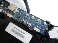
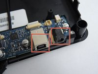
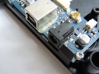
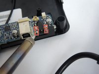
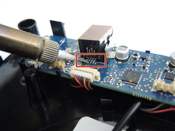
跳转到主内容

M3D Micro Data and Power Port Replacement

你所需要的

  1. M3D Micro Data and Power Port Replacement, Data and Power Ports: 步骤 1 中的图像 1,3 M3D Micro Data and Power Port Replacement, Data and Power Ports: 步骤 1 中的图像 2,3 M3D Micro Data and Power Port Replacement, Data and Power Ports: 步骤 1 中的图像 3,3
    • Place pressure on the central print bed and simultaneously pull up on the outer perimeter of the 3D printer. The cube shaped enclosure will lift up.

  2. M3D Micro Data and Power Port Replacement: 步骤 2 中的图像 1,3 M3D Micro Data and Power Port Replacement: 步骤 2 中的图像 2,3 M3D Micro Data and Power Port Replacement: 步骤 2 中的图像 3,3
    • Remove the print bed cover and locate the four screws holding the print bed to the base of the unit. Remove the four 9.5 mm screws using the 3.5 Hex head from the bit kit.

  3. M3D Micro Data and Power Port Replacement: 步骤 3 中的图像 1,2 M3D Micro Data and Power Port Replacement: 步骤 3 中的图像 2,2
    • Lifting the print bed reveals the motherboard that controls the unit. This is the hardware that allows the printer to connect to the computer. The port on the left is the data and the port on the right is the power input.

  4. M3D Micro Data and Power Port Replacement: 步骤 4 中的图像 1,3 M3D Micro Data and Power Port Replacement: 步骤 4 中的图像 2,3 M3D Micro Data and Power Port Replacement: 步骤 4 中的图像 3,3
    • The ports are primarily soldered on to the board but are additionally secured using glue. Use the sharp metal spudger tool to gently pry apart the glue surrounding the ports.

  5. M3D Micro Data and Power Port Replacement: 步骤 5 中的图像 1,2 M3D Micro Data and Power Port Replacement: 步骤 5 中的图像 2,2
    • To remove the charging port grasp the port with a pair of pliers and use a soldering iron to desolder the joints at the red marks while carefully pulling away with the pliers.

  6. M3D Micro Data and Power Port Replacement: 步骤 6 中的图像 1,2 M3D Micro Data and Power Port Replacement: 步骤 6 中的图像 2,2
    • To replace the power port, match the four contact points on the board to the new port and carefully solder the components together.

  7. M3D Micro Data and Power Port Replacement: 步骤 7 中的图像 1,2 M3D Micro Data and Power Port Replacement: 步骤 7 中的图像 2,2
    • To replace the USB data port, follow the same procedure as Step 5. The contact pins for the data port are on the back. The red marker indicates the four contact pins that must be matched up and carefully soldered on.

结论

To reassemble your device, follow these instructions in reverse order.

Ilian D

于09/28/17注册

125 声望

撰写一个指南

团队

USF Tampa, Team S3-G2, Nance Fall 2017 USF Tampa, Team S3-G2, Nance Fall 2017 的会员

USFT-NANCE-F17S3G2

4 名成员

创作了10篇指南

2条评论

Between the 2nd & 3rd images in step 1, the print head has vanished without explanation.

How do we remove the print head so we can remove the top half of the case to be able to proceed to step 2?

That’s the only piece if data missing.

Otherwise, it seems to be a great article.

Thank you.

Justin Hamilton - 回复

I found this document to replace the Z-Belt. It includes the steps to remove the print head.
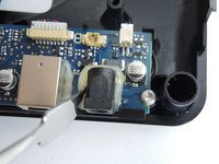
https://micro.printm3d.com/technical-sup...

Justin Hamilton - 回复

添加评论

浏览统计数据:

过去 24 小时: 1

过去 7 天: 8

过去 30 天: 15

总计 1,777