简介
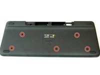
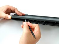
This guide will teach you to remove and replace the Logitech Harmony Smart Keyboard's Touchpad PCB.
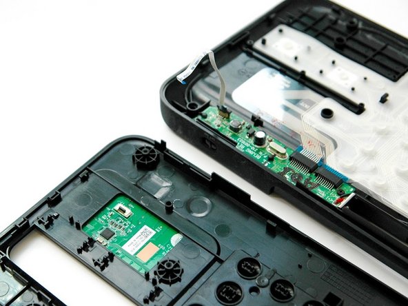
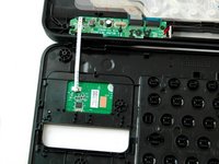
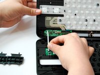
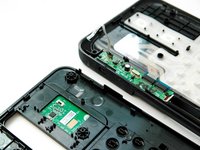
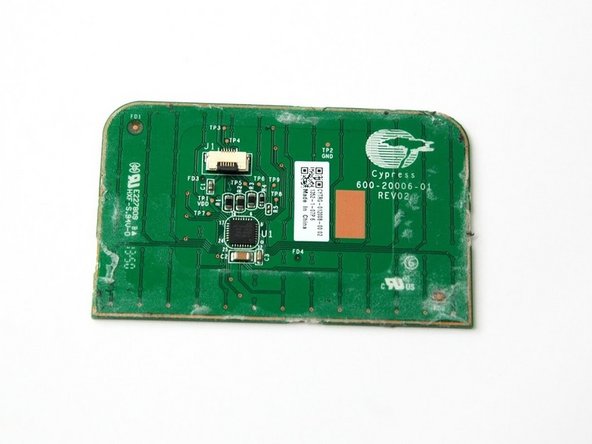
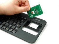
The printed circuit board (PCB) mechanically assists and electrically connects electronic parts using conductive tracks, pads and other components. The PCB appears in the form of a thin, copper board.
你所需要的
-
-
-
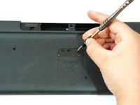
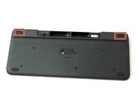
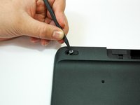
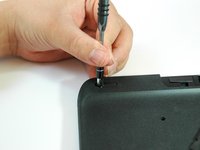
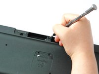
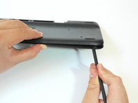
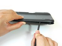
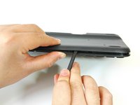
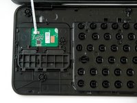
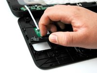
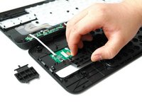
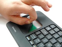
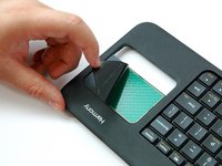
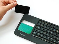
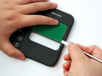
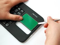
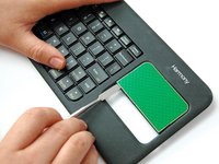
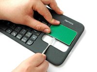
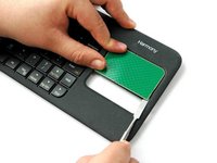
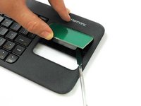
Lift up and pull off the track pad’s left and right clickers.
-


结论
To reassemble your device, follow these instructions in reverse order.
团队

CSU Fullerton, Team S1-G2, Bruce Fall 2017 CSU Fullerton, Team S1-G2, Bruce Fall 2017 的会员
CSUF-BRUCE-F17S1G2
3 名成员
创作了10篇指南