跳转到主内容

Linksys WRT54G Motherboard Component Replacement

你所需要的

  1. Linksys WRT54G Motherboard Component Replacement, Antennas: 步骤 1 中的图像 1,1
    • Unfold the antennas straight away from the device.

  2. Linksys WRT54G Motherboard Component Replacement: 步骤 2 中的图像 1,3 Linksys WRT54G Motherboard Component Replacement: 步骤 2 中的图像 2,3 Linksys WRT54G Motherboard Component Replacement: 步骤 2 中的图像 3,3
    • Remove the black caps from the antennas by pulling them away from the device.

  3. Linksys WRT54G Motherboard Component Replacement: 步骤 3 中的图像 1,3 Linksys WRT54G Motherboard Component Replacement: 步骤 3 中的图像 2,3 Linksys WRT54G Motherboard Component Replacement: 步骤 3 中的图像 3,3
    • Unscrew each of the antennas from the wireless device.

  4. Linksys WRT54G Motherboard Component Replacement, Casing: 步骤 4 中的图像 1,2 Linksys WRT54G Motherboard Component Replacement, Casing: 步骤 4 中的图像 2,2
    • Using a bit of force, remove the blue plastic case.

  5. Linksys WRT54G Motherboard Component Replacement, Motherboard: 步骤 5 中的图像 1,2 Linksys WRT54G Motherboard Component Replacement, Motherboard: 步骤 5 中的图像 2,2
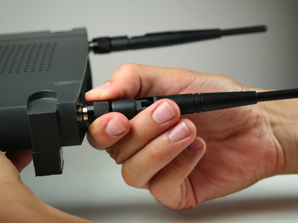
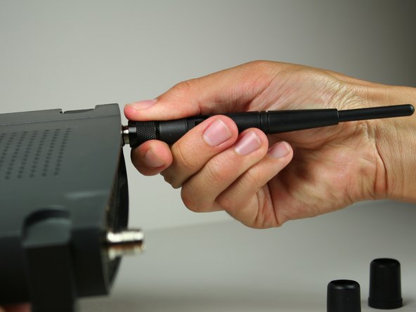
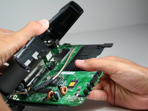
    • To remove the black casing that surrounds the green motherboard, slide the top half of the casing backwards. It only moves a very short distance.

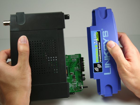
    • Pull the top piece upwards and away from the bottom to remove.

  6. Linksys WRT54G Motherboard Component Replacement: 步骤 6 中的图像 1,2 Linksys WRT54G Motherboard Component Replacement: 步骤 6 中的图像 2,2
    • Locate the 2 M2.5x6mm screws that attach the motherboard to the back case.

    • Remove the two screws from the motherboard as indicated with the Phillips head screwdriver.

  7. Linksys WRT54G Motherboard Component Replacement: 步骤 7 中的图像 1,1
    • Once screws have been removed, slide the motherboard in the direction of its LED lights.

    • Lift motherboard up and away from the black lower casing.

  8. Linksys WRT54G Motherboard Component Replacement, Motherboard Component: 步骤 8 中的图像 1,1
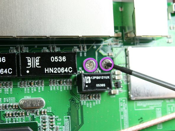
    • Obtain a desoldering wick (Desoldering Braid). Plug in soldering iron and allow to heat. For soldering information, refer to the iFixit soldering guide (如何焊接和拆焊).

    • Make sure that the soldering iron is not resting on top of anything that would be damaged by the heat.

  9. Linksys WRT54G Motherboard Component Replacement: 步骤 9 中的图像 1,2 Linksys WRT54G Motherboard Component Replacement: 步骤 9 中的图像 2,2
    • Identify the functional component which will be removed.

    • Turn the board over so that the pins holding the component in are exposed.

  10. Linksys WRT54G Motherboard Component Replacement: 步骤 10 中的图像 1,1
    • Desolder each pin using the iFixit Soldering Guide (如何焊接和拆焊). Gently remove functional component for replacement.

结论

To reassemble your device, follow these instructions in reverse order.

另外一个人完成了本指南。

Nicole C

于10/12/11注册

102 声望

撰写一个指南

团队

Cal Poly, Team 17-7, Regan Fall 2011 Cal Poly, Team 17-7, Regan Fall 2011 的会员

CPSU-REGAN-F11S17G7

4 名成员

创作了4篇指南

0条评论

添加评论

浏览统计数据:

过去 24 小时: 0

过去 7 天: 0

过去 30 天: 2

总计 3,849