当前版本的文档还未经巡查,您可以查看最新的已查核版本 。
Insert a SIM eject tool, bit, or a straightened paper clip into the small hole on the SIM card tray on the left edge of the phone.
Press firmly to eject the tray.
Remove the SIM card tray.
Slide the opening pick across the bottom towards the left corner to slice the adhesive.
With the pick still inserted, slide it from the bottom left corner over to the bottom right corner to completely slice the bottom side adhesive.
Leave the pick inserted in the bottom right corner to prevent the adhesive from re-sealing.
Slide the opening pick around the bottom left corner and across the left side of the phone to slice the adhesive.
The adhesive can be very gummy. Push the pick in and out in a sawing motion to help with slicing.
Stop when you reach the top left corner, near the camera, and leave the pick inserted.
With the first two opening picks still in place, insert a third pick on the lower part of the righthand side.
Slide the opening pick up towards the top of the phone, slicing the right side's adhesive.
Stop when you reach the top right corner, and leave the pick inserted.
Once you have sliced around the perimeter of the phone, carefully lift the right edge of the back cover, opening it like a book.
Do not try to pull the panel all the way off yet, as it is still connected to the phone.
Continue swinging open the back panel until you can rest it on the left edge the phone, being careful not to put any stress on the attached ribbon cable.
During reassembly, this is a good point to power on your phone and test all functions before re-sealing the back panel. Be sure to power your phone back down completely before you continue working.
在这个步骤中使用的工具:
Magnetic Project Mat
$19.95
购买
Remove the five T3 Torx screws securing the battery connector shield:
Four 4.0 mm screws
One 2.1 mm screw
Throughout this repair, keep track of each screw and make sure it goes back exactly where it came from.
Whenever you use the spudger near the battery, be very careful not to puncture the battery.
Using the pointed end of a spudger, pry the battery connector straight up from the motherboard to disconnect the battery.
To re-attach press connectors like this one, carefully align and press down on one side until it clicks into place, then repeat on the other side. Do not press down on the middle. If the connector is misaligned, the pins can bend, causing permanent damage.
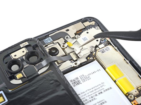
The LED flash module is secured to the back panel underneath a graphite adhesive layer which will need to be removed.
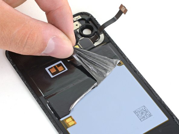
Use tweezers on one of the bottom corners to pull up the adhesive enough to grab it with your fingers.
Peel back the graphite adhesive layer to expose the wireless charging coil, NFC pads, and LED flash module.
Completely remove the graphite adhesive layer.
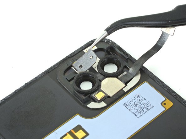
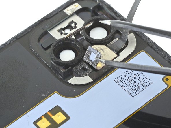
All sections of the flash module are secured to the back panel with some light adhesive.
Use a pair of tweezers to gently pry up and peel back the spectral and flicker sensor portion of the flash module.
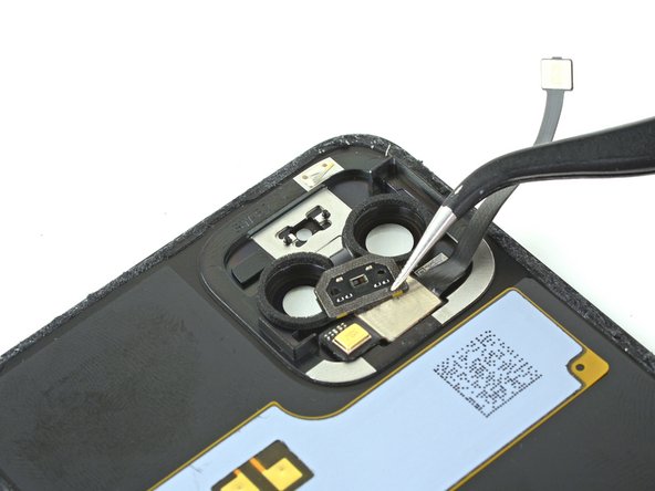
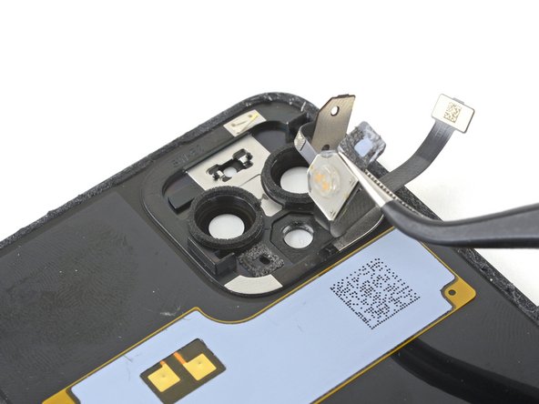
Use a pair of tweezers or the pointed end of a spudger to peel up the back panel's microphone.
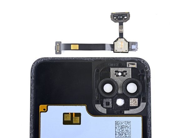
Before you install a replacement LED flash module, check the microphone's adhesive gasket:
If it is in good condition, you can re-use the gasket. Make sure that the gasket does not cover the hole.
If the gasket is pulled out of place, remove it and replace the adhesive with a pre-cut strip or Tesa tape.
嵌入本指南
选择一个尺寸并复制下面的代码,将本指南作为一个小插件嵌入到你的网站/论坛中。
单个步骤
完整指南
小——600像素
中——800像素
大——1200像素
预览