跳转到主内容

当前版本的文档还未经巡查,您可以查看最新的已查核版本

仅作为前提条件
本指南仅用作其他指南的先决条件。不能单独食用。

你所需要的

  1. 这个步骤还没有翻译 帮忙翻译一下

    : 步骤 1 中的图像 1,3 : 步骤 1 中的图像 2,3 : 步骤 1 中的图像 3,3
    • Insert a SIM eject tool, bit, or a straightened paper clip into the small hole on the SIM card tray on the left edge of the phone.

    • Press firmly to eject the tray.

    • Remove the SIM card tray.

  2. , 加热背板玻璃: 步骤 2 中的图像 1,1
    • 准备一个Prepare an iOpener 并将其敷在背板的底部边缘处一分钟

    • 也可以使用吹风机,热枪或热板,但小心不要过度加热手机 - 因为显示器和内部电池都易受热损坏。

  3. , 安好吸盘: 步骤 3 中的图像 1,2 , 安好吸盘: 步骤 3 中的图像 2,2
    • 通过向下压下将吸盘施加到后面板的加热边缘,以尽可能靠近边缘产生吸力。

    • 如果您的背玻璃严重破裂,用胶带覆盖它可能会帮助吸盘粘附。或者,可以使用粘性大的胶带带代替吸盘。如果这些方法都失败了,你还可以将超强胶水和吸盘一同并用。

  4. , 插入一个三角撬片: 步骤 4 中的图像 1,2 , 插入一个三角撬片: 步骤 4 中的图像 2,2
    • 以强大,稳定的力拉上吸盘,使后面板和框架之间产生间隙。

    • 根据手机的老化程度,这可能很困难。如果你遇到问题,再次加热手机边缘,然后再试一次。

    • 将三角撬片插入间隙

  5. 这个步骤还没有翻译 帮忙翻译一下

    : 步骤 5 中的图像 1,3 : 步骤 5 中的图像 2,3 : 步骤 5 中的图像 3,3
    • Slide the opening pick across the bottom towards the left corner to slice the adhesive.

    • With the pick still inserted, slide it from the bottom left corner over to the bottom right corner to completely slice the bottom side adhesive.

    • Leave the pick inserted in the bottom right corner to prevent the adhesive from re-sealing.

  6. 这个步骤还没有翻译 帮忙翻译一下

    : 步骤 6 中的图像 1,1
    • Prepare an iOpener and apply it on the left edge of the phone for one minute.

  7. 这个步骤还没有翻译 帮忙翻译一下

    : 步骤 7 中的图像 1,2 : 步骤 7 中的图像 2,2
    • Insert a second opening pick underneath the back panel directly over the charge port.

    • Slide the opening pick to the bottom left corner of the phone.

  8. 这个步骤还没有翻译 帮忙翻译一下

    : 步骤 8 中的图像 1,2 : 步骤 8 中的图像 2,2
    • Slide the opening pick around the bottom left corner and across the left side of the phone to slice the adhesive.

    • The adhesive can be very gummy. Push the pick in and out in a sawing motion to help with slicing.

    • Stop when you reach the top left corner, near the camera, and leave the pick inserted.

  9. 这个步骤还没有翻译 帮忙翻译一下

    : 步骤 9 中的图像 1,1
    • Prepare an iOpener and apply it on the right edge of the phone for one minute.

  10. 这个步骤还没有翻译 帮忙翻译一下

    : 步骤 10 中的图像 1,3 : 步骤 10 中的图像 2,3 : 步骤 10 中的图像 3,3
    • With the first two opening picks still in place, insert a third pick on the lower part of the righthand side.

    • Slide the opening pick up towards the top of the phone, slicing the right side's adhesive.

    • Stop when you reach the top right corner, and leave the pick inserted.

  11. 这个步骤还没有翻译 帮忙翻译一下

    : 步骤 11 中的图像 1,2 : 步骤 11 中的图像 2,2
    • Slide the third opening pick around the top right corner and across the top side of the phone, slicing the final strip of adhesive.

  12. 这个步骤还没有翻译 帮忙翻译一下

    : 步骤 12 中的图像 1,3 : 步骤 12 中的图像 2,3 : 步骤 12 中的图像 3,3
    • Once you have sliced around the perimeter of the phone, carefully lift the right edge of the back cover, opening it like a book.

    • Do not try to pull the panel all the way off yet, as it is still connected to the phone.

  13. 这个步骤还没有翻译 帮忙翻译一下

    : 步骤 13 中的图像 1,2 : 步骤 13 中的图像 2,2
    • Continue swinging open the back panel until you can rest it on the left edge the phone, being careful not to put any stress on the attached ribbon cable.

    • During reassembly, this is a good point to power on your phone and test all functions before re-sealing the back panel. Be sure to power your phone back down completely before you continue working.

  14. 这个步骤还没有翻译 帮忙翻译一下

    : 步骤 14 中的图像 1,1
    在这个步骤中使用的工具:
    Magnetic Project Mat
    $19.95
    购买
    • Remove the five T3 Torx screws securing the battery connector shield:

    • Four 4.0 mm screws

    • One 2.1 mm screw

    • Throughout this repair, keep track of each screw and make sure it goes back exactly where it came from.

  15. 这个步骤还没有翻译 帮忙翻译一下

    : 步骤 15 中的图像 1,2 : 步骤 15 中的图像 2,2
    • Use a pair of tweezers to remove the battery connector shield.

  16. 这个步骤还没有翻译 帮忙翻译一下

    : 步骤 16 中的图像 1,2 : 步骤 16 中的图像 2,2
    • Whenever you use the spudger near the battery, be very careful not to puncture the battery.

    • Using the pointed end of a spudger, pry the battery connector straight up from the motherboard to disconnect the battery.

    • To re-attach press connectors like this one, carefully align and press down on one side until it clicks into place, then repeat on the other side. Do not press down on the middle. If the connector is misaligned, the pins can bend, causing permanent damage.

  17. 这个步骤还没有翻译 帮忙翻译一下

    : 步骤 17 中的图像 1,2 : 步骤 17 中的图像 2,2
    • Using the flat end of a spudger, gently fold the battery cable over so it doesn't accidentally make contact during the rest of your repairs.

  18. 这个步骤还没有翻译 帮忙翻译一下

    : 步骤 18 中的图像 1,1
    • Use a T3 Torx driver to remove the two 4 mm screws securing the back panel connector cover.

  19. 这个步骤还没有翻译 帮忙翻译一下

    : 步骤 19 中的图像 1,2 : 步骤 19 中的图像 2,2
    • Use a pair of tweezers to remove the back panel connector cover.

  20. 这个步骤还没有翻译 帮忙翻译一下

    : 步骤 20 中的图像 1,2 : 步骤 20 中的图像 2,2
    • Using the pointed end of a spudger, pry up and disconnect the back panel connector.

  21. 这个步骤还没有翻译 帮忙翻译一下

    : 步骤 21 中的图像 1,1
    • Remove the back panel.

    • During reassembly, follow this guide to install custom-cut adhesives for your device.

    • Follow this guide if you are using a pre-cut adhesive card.

  22. 这个步骤还没有翻译 帮忙翻译一下

    : 步骤 22 中的图像 1,3 : 步骤 22 中的图像 2,3 : 步骤 22 中的图像 3,3
    • Pull on the yellow pull tab of the adhesive strip with steady force.

    • If the adhesive becomes hard to pull, you can roll it around a spudger and continue pulling.

    • Continue firmly pulling up on the adhesive strip with constant force. If you're using a spudger, spin it every so often to keep the exposed section of the pull tab as short as possible.

    • This may take a lot of force.

    • These adhesive pull tabs are very prone to snapping in half during this process. Pull as slowly as possible.

    • If the adhesive pull tabs are not stretching, fill a plastic dropper or syringe with high concentration (>90%) isopropyl alcohol and apply a few drops under the left edge of the battery. Give the alcohol a minute to weaken the battery adhesive.

    • Continue this process for each of the three pull tabs, until all are either out or have snapped in half.

  23. 这个步骤还没有翻译 帮忙翻译一下

    : 步骤 23 中的图像 1,2 : 步骤 23 中的图像 2,2
    • If the battery tabs snapped during removal, insert an opening pick on the upper right edge of the battery, slicing the adhesive underneath.

    • Even if you successfully removed all three adhesive pull tabs, using an opening pick to dislodge the battery may be helpful.

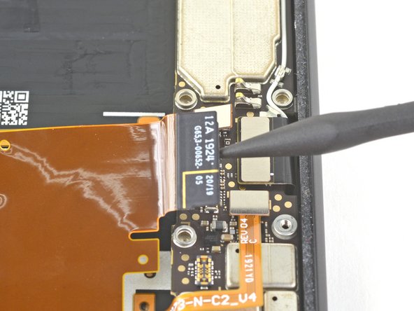
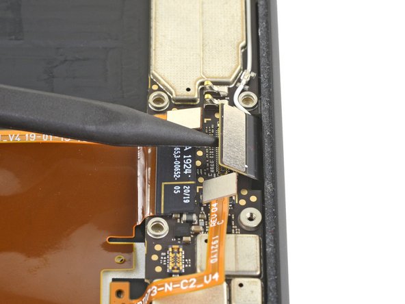
    • Don't insert the opening pick on or anywhere below the grip sensor cable, as the pick can damage the charge port flex cable located underneath the battery.

  24. 这个步骤还没有翻译 帮忙翻译一下

    : 步骤 24 中的图像 1,2 : 步骤 24 中的图像 2,2
    在这个步骤中使用的工具:
    Tesa 61395 Tape
    $5.99
    购买
    • Do not reuse the battery if it has been deformed or damaged, as doing so is a potential safety hazard. Replace it with a new battery.

    • Lift the battery up and away from the phone to remove it. You may need to peel the battery away from any leftover adhesive tabs.

    • If there's any alcohol solution remaining in the phone, carefully wipe it off with a lint-free cloth or allow it to air dry before installing your battery.

    • To install a replacement battery:

    • If you're using stretch release adhesive, apply them onto the battery. Otherwise, apply some double-sided tape, or pre-cut adhesive strips in the phone's battery well, being careful not to cover the charge port flex cable. Peel away any tape liners to expose the adhesive.

    • Temporarily re-connect the battery's connector to the motherboard socket. This ensures that the battery is properly positioned.

    • Lay the battery in place and press firmly.

    • Disconnect the battery connector from its motherboard socket and resume re-assembly.

  25. 这个步骤还没有翻译 帮忙翻译一下

    : 步骤 25 中的图像 1,1
    • Use a T3 Torx driver to remove the four 4 mm screws securing the camera connector cover.

  26. 这个步骤还没有翻译 帮忙翻译一下

    : 步骤 26 中的图像 1,3 : 步骤 26 中的图像 2,3 : 步骤 26 中的图像 3,3
    • Using a pair of tweezers, tilt the camera cover up and slide it out of the retaining slot on the upper right corner of the phone to remove.

  27. 这个步骤还没有翻译 帮忙翻译一下

    : 步骤 27 中的图像 1,3 : 步骤 27 中的图像 2,3 : 步骤 27 中的图像 3,3
    • Using the pointed end of a spudger, pry the camera and sensor connectors straight up from the motherboard.

  28. 这个步骤还没有翻译 帮忙翻译一下

    : 步骤 28 中的图像 1,2 : 步骤 28 中的图像 2,2
    • Disconnect the additional sensor connector.

  29. 这个步骤还没有翻译 帮忙翻译一下

    : 步骤 29 中的图像 1,1
    • Use a T3 Torx driver to remove the two 2.4 mm screws securing the front camera and sensor assembly.

  30. 这个步骤还没有翻译 帮忙翻译一下

    : 步骤 30 中的图像 1,2 : 步骤 30 中的图像 2,2
    • Use a pair of tweezers to remove the front camera and sensor assembly.

  31. 这个步骤还没有翻译 帮忙翻译一下

    : 步骤 31 中的图像 1,1
    • Remove the two T3 Torx screws securing the vibration motor cover:

    • One 4.2 mm screw

    • One 4.4 mm shouldered screw

  32. 这个步骤还没有翻译 帮忙翻译一下

    : 步骤 32 中的图像 1,2 : 步骤 32 中的图像 2,2
    • Use a pair of tweezers to remove the vibration motor shield.

  33. 这个步骤还没有翻译 帮忙翻译一下

    : 步骤 33 中的图像 1,3 : 步骤 33 中的图像 2,3 : 步骤 33 中的图像 3,3
    • Use the pointed end of a spudger to disconnect the two rear-facing camera connectors from the motherboard.

    • Disconnect the side buttons connector from the motherboard.

  34. 这个步骤还没有翻译 帮忙翻译一下

    : 步骤 34 中的图像 1,2 : 步骤 34 中的图像 2,2
    • Disconnect the earpiece speaker connector from the motherboard.

  35. 这个步骤还没有翻译 帮忙翻译一下

    : 步骤 35 中的图像 1,3 : 步骤 35 中的图像 2,3 : 步骤 35 中的图像 3,3
    • Disconnect the left grip sensor connector from the motherboard.

    • Disconnect the charge port connector from the motherboard.

  36. 这个步骤还没有翻译 帮忙翻译一下

    : 步骤 36 中的图像 1,2 : 步骤 36 中的图像 2,2
    • Disconnect the right grip sensor connector from the motherboard.

    • Disconnect the display connector from the motherboard.

  37. 这个步骤还没有翻译 帮忙翻译一下

    : 步骤 37 中的图像 1,2 : 步骤 37 中的图像 2,2
    • Use a pair of tweezers to disconnect the antenna connector from the charging assembly by pulling it straight up from the motherboard.

  38. 这个步骤还没有翻译 帮忙翻译一下

    : 步骤 38 中的图像 1,2 : 步骤 38 中的图像 2,2
    • Disconnect the bottom microphone connector from the motherboard.

  39. 这个步骤还没有翻译 帮忙翻译一下

    : 步骤 39 中的图像 1,3 : 步骤 39 中的图像 2,3 : 步骤 39 中的图像 3,3
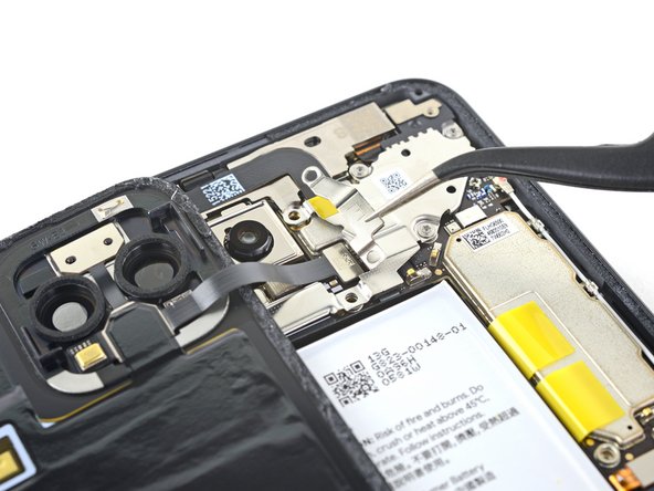
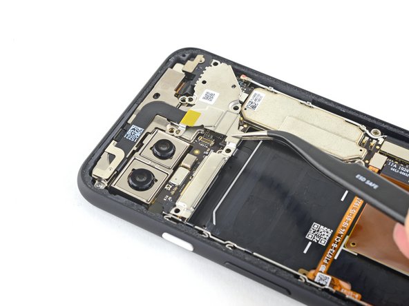
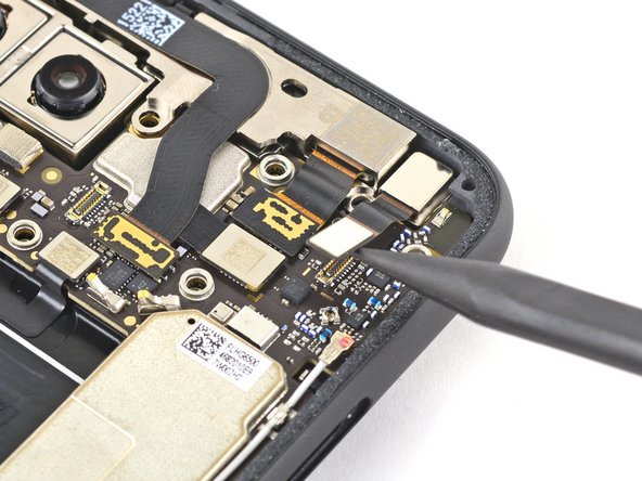
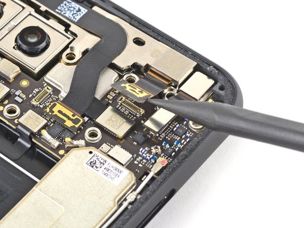
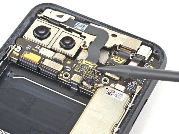
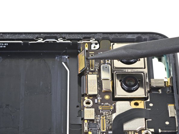
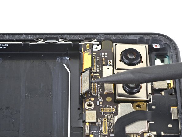
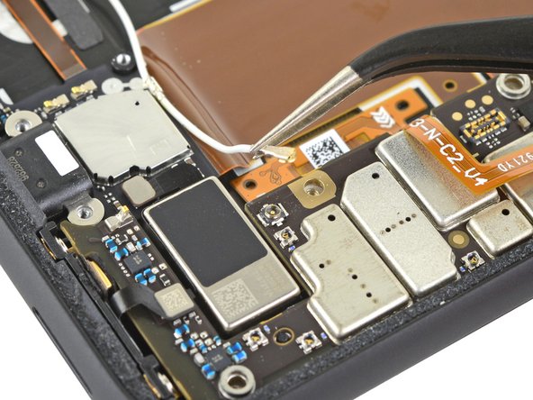
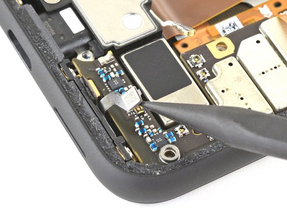
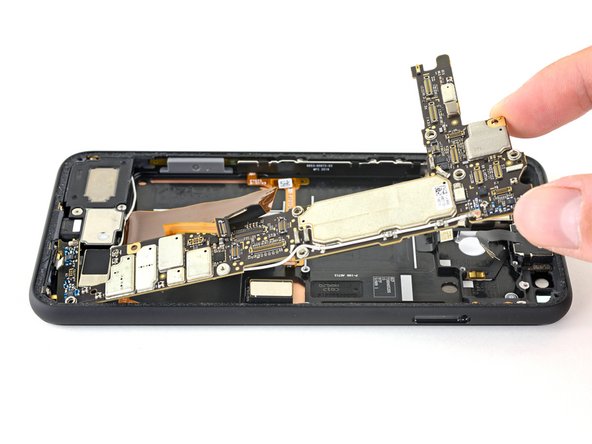
    • Slowly lift out the motherboard, being careful not to snag any ribbon cable connectors.

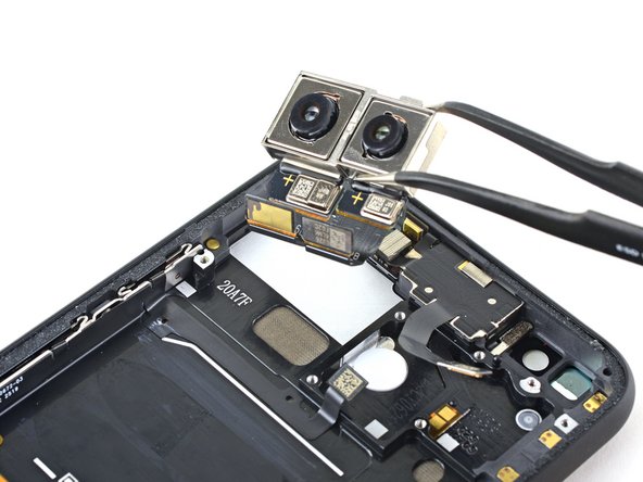
    • The rear-facing camera module connectors loop around the motherboard, and the camera module is not secured to the phone, so it may lift out with the motherboard during this step.

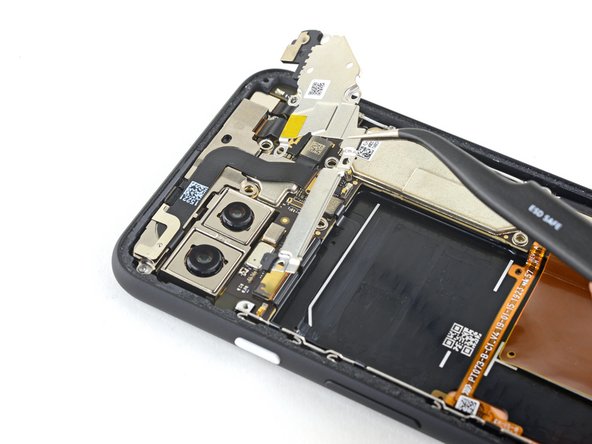
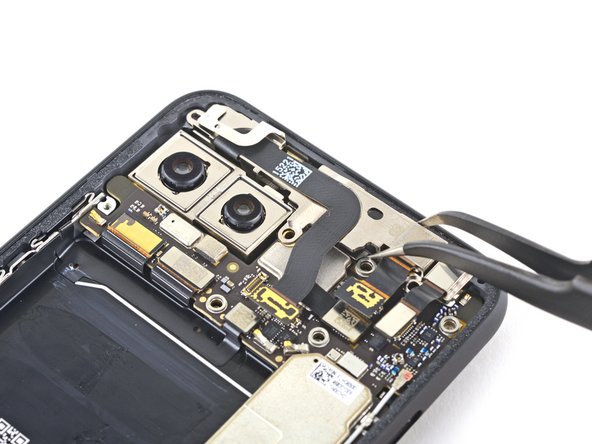
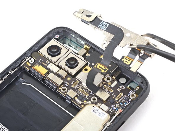
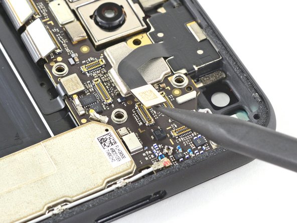
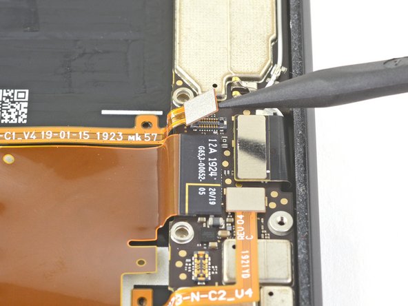
    • Completely remove the motherboard.

    • When reinstalling the motherboard, check that no ribbon cable connectors are caught underneath.

  40. 这个步骤还没有翻译 帮忙翻译一下

    : 步骤 40 中的图像 1,2 : 步骤 40 中的图像 2,2
    • Use a pair of tweezers to remove the rear-facing camera module.

终点

Carsten Frauenheim

于03/10/20注册

113,672 声望

创作了338篇指南

团队

iFixit iFixit 的会员

Staff

135 名成员

创作了16,817篇指南

0条评论

添加评论

浏览统计数据:

过去 24 小时: 0

过去 7 天: 0

过去 30 天: 0

总计 57