当前版本的文档还未经巡查,您可以查看最新的已查核版本。
你所需要的
-
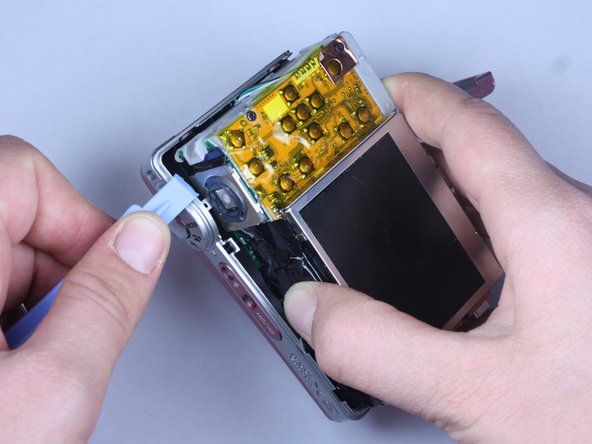
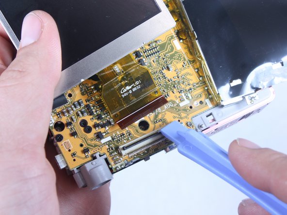
这个步骤还没有翻译 帮忙翻译一下
-
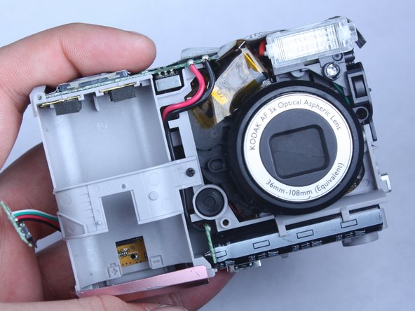
Before removing back cover, it is advisable to use an anti-static wrist strap to prevent damage to electronics.
-
-
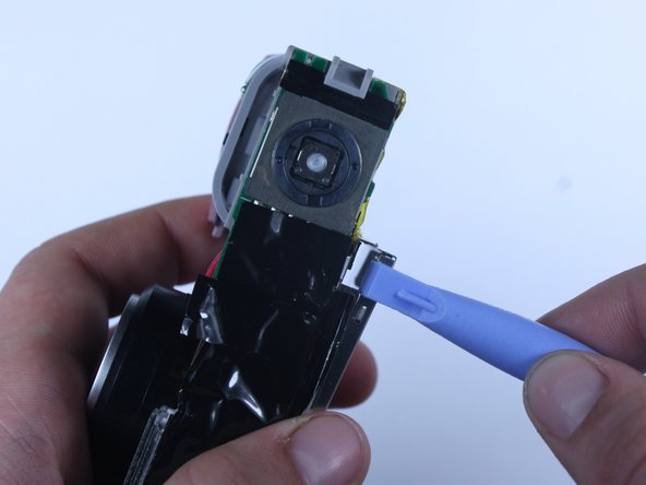
这个步骤还没有翻译 帮忙翻译一下
-
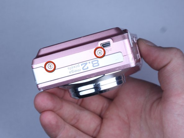
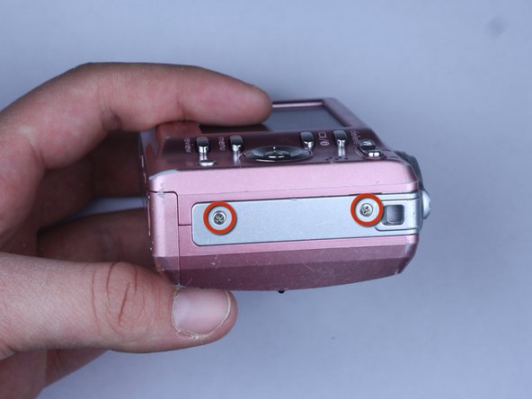
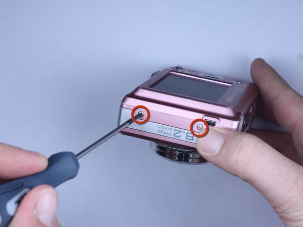
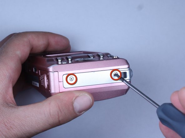
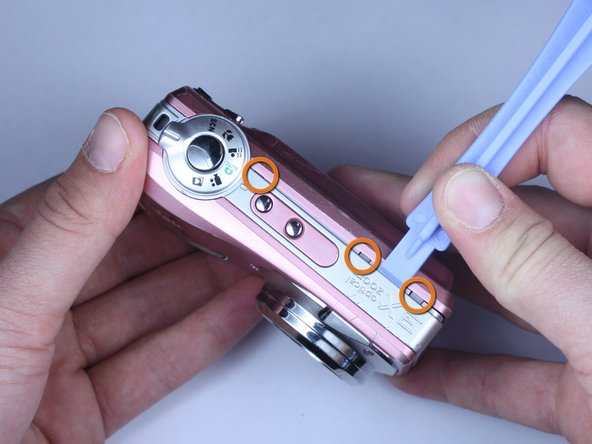
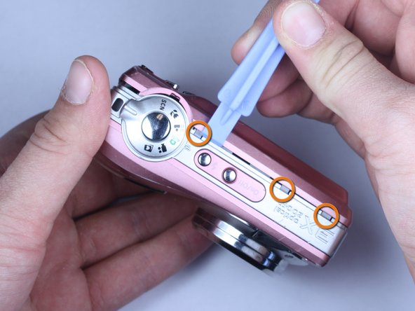
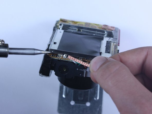
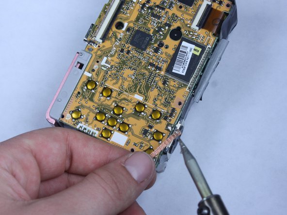
Remove all 7 screws:
-
Hold the camera firmly with one hand so that you can still see a screw.
-
Place the Philips 00(Found here)screwdriver into the screw.
-
Turn the screwdriver to the left until it is free.
-
Repeat for the remaining screws.
-
-


即将完成!
终点
团队

Cal Poly, Team 24-22, Regan Spring 2010 Cal Poly, Team 24-22, Regan Spring 2010 的会员
CPSU-REGAN-S10S24G22
4 名成员
创作了20篇指南