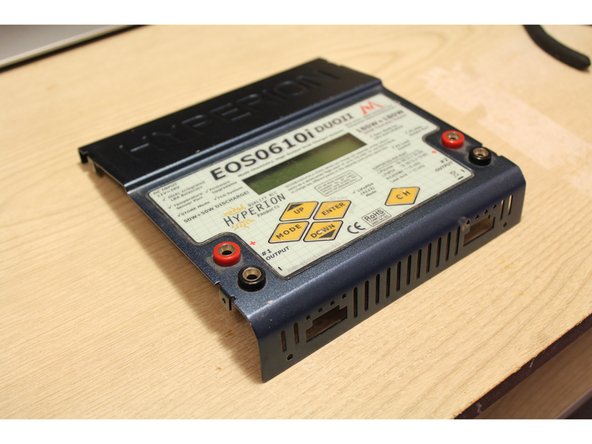
跳转到主内容

Disassembling Hyperion EOS0610i DUOII Chassis

你所需要的

  1. Disassembling Hyperion EOS0610i DUOII Chassis, Disconnect DC Power: 步骤 1 中的图像 1,2 Disassembling Hyperion EOS0610i DUOII Chassis, Disconnect DC Power: 步骤 1 中的图像 2,2
    • Disconnect the DC power banana plugs from any power source.

    • When not powered, the chargers screen will be blank.

  2. Disassembling Hyperion EOS0610i DUOII Chassis, Remove Balance Boards: 步骤 2 中的图像 1,3 Disassembling Hyperion EOS0610i DUOII Chassis, Remove Balance Boards: 步骤 2 中的图像 2,3 Disassembling Hyperion EOS0610i DUOII Chassis, Remove Balance Boards: 步骤 2 中的图像 3,3
    • Press down on the tab located on the top of the white molex connector and firmly pull away from the charger body.

  3. Disassembling Hyperion EOS0610i DUOII Chassis, Remove Right Side Panel: 步骤 3 中的图像 1,3 Disassembling Hyperion EOS0610i DUOII Chassis, Remove Right Side Panel: 步骤 3 中的图像 2,3 Disassembling Hyperion EOS0610i DUOII Chassis, Remove Right Side Panel: 步骤 3 中的图像 3,3
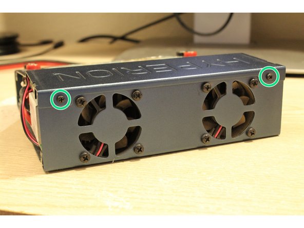
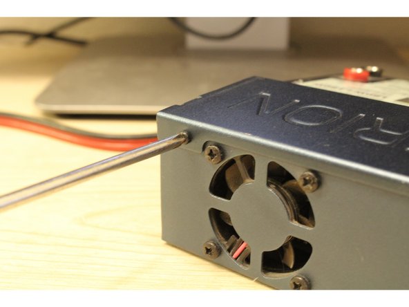
    • Remove the four screws located on the right side cover of the charger.

  4. Disassembling Hyperion EOS0610i DUOII Chassis, Remove Left Side Panel Screws: 步骤 4 中的图像 1,3 Disassembling Hyperion EOS0610i DUOII Chassis, Remove Left Side Panel Screws: 步骤 4 中的图像 2,3 Disassembling Hyperion EOS0610i DUOII Chassis, Remove Left Side Panel Screws: 步骤 4 中的图像 3,3
    • Remove the four screws located on the right side panel.

    • Do not pull on the panel, the DC power cables are rigidly attached to the panel by the black plastic grommet, this grommet is removed in the next step.

  5. Disassembling Hyperion EOS0610i DUOII Chassis, Remove the DC Power Cable Grommet: 步骤 5 中的图像 1,3 Disassembling Hyperion EOS0610i DUOII Chassis, Remove the DC Power Cable Grommet: 步骤 5 中的图像 2,3 Disassembling Hyperion EOS0610i DUOII Chassis, Remove the DC Power Cable Grommet: 步骤 5 中的图像 3,3
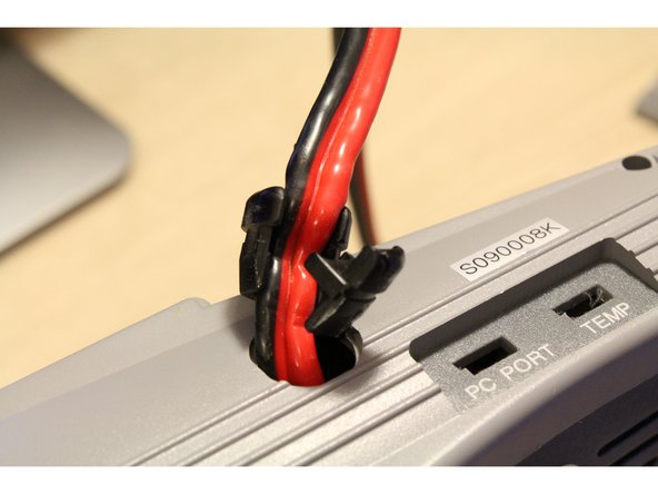
    • Locate the smaller, secondary part of the grommet.

    • Using needle nose pliers, gently sqeeze on the secondary part of the grommet and the opposite side of the grommet while pushing the grommet through the hole towards the exterior side of the panel.

    • Once pushed through the hole, the grommet can be removed from the wires and set aside.

    • The smaller, secondary part of the grommet is connected to the main part of the grommet by a thin piece of plastic, ensure this piece is not severed during this process.

  6. Disassembling Hyperion EOS0610i DUOII Chassis, Pass the DC Power Cables through the Left Side Panel: 步骤 6 中的图像 1,3 Disassembling Hyperion EOS0610i DUOII Chassis, Pass the DC Power Cables through the Left Side Panel: 步骤 6 中的图像 2,3 Disassembling Hyperion EOS0610i DUOII Chassis, Pass the DC Power Cables through the Left Side Panel: 步骤 6 中的图像 3,3
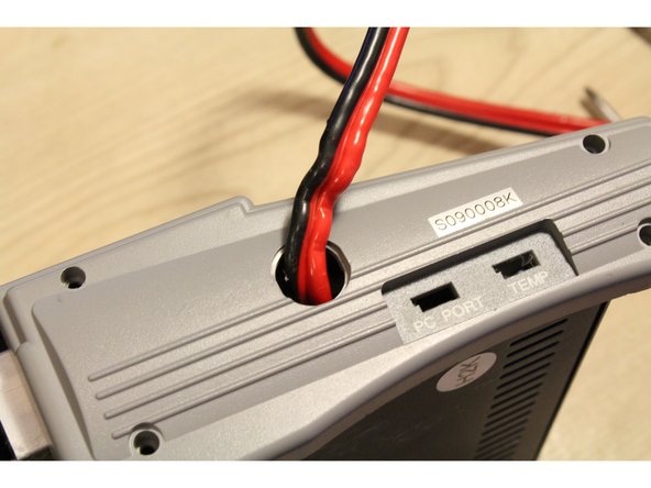
    • One by one, pass both banana connectors through the hole in the left side panel.

  7. Disassembling Hyperion EOS0610i DUOII Chassis, Remove Top Face Cover Screws: 步骤 7 中的图像 1,3 Disassembling Hyperion EOS0610i DUOII Chassis, Remove Top Face Cover Screws: 步骤 7 中的图像 2,3 Disassembling Hyperion EOS0610i DUOII Chassis, Remove Top Face Cover Screws: 步骤 7 中的图像 3,3
    • Remove the two screws located on the front side of the charger.

    • Remove the two screws located on the back side of the charger, above the fan screws.

  8. Disassembling Hyperion EOS0610i DUOII Chassis, Desolder the Charge Ports: 步骤 8 中的图像 1,2 Disassembling Hyperion EOS0610i DUOII Chassis, Desolder the Charge Ports: 步骤 8 中的图像 2,2
    • Desolder the two wires connected to the female banana plug ports for both channel 1 and 2 (left and ride sides of the charger).

    • Too high temperature setting will cause the plastic banana plug port covers to melt, use only as much heat as needed to flow the solder.

  9. Disassembling Hyperion EOS0610i DUOII Chassis, Gently Lift the Top Cover: 步骤 9 中的图像 1,2 Disassembling Hyperion EOS0610i DUOII Chassis, Gently Lift the Top Cover: 步骤 9 中的图像 2,2
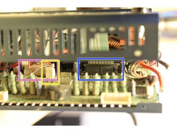
    • The top cover is still connected by three ribbon cables to the mainboard. Gently lift the top cover until you can slide your fingers or a spudger into the charger to disconnect the three molex connectors.

    • LCD Segment Display Connector

    • Backlight Power Connector

    • Front Panel Buttons Ribbon

  10. Disassembling Hyperion EOS0610i DUOII Chassis, Disconnect Top Plate Ribbon Cables: 步骤 10 中的图像 1,3 Disassembling Hyperion EOS0610i DUOII Chassis, Disconnect Top Plate Ribbon Cables: 步骤 10 中的图像 2,3 Disassembling Hyperion EOS0610i DUOII Chassis, Disconnect Top Plate Ribbon Cables: 步骤 10 中的图像 3,3
    • Use a spudger or shim to gently separate the top plastic bar from the large lower piece. Once separated, the ribon cable can be slipped out of the housing.

    • Disconnect the two white molex connectors from the board mount plugs.

  11. Disassembling Hyperion EOS0610i DUOII Chassis, Separate Upper and Lower Portions: 步骤 11 中的图像 1,3 Disassembling Hyperion EOS0610i DUOII Chassis, Separate Upper and Lower Portions: 步骤 11 中的图像 2,3 Disassembling Hyperion EOS0610i DUOII Chassis, Separate Upper and Lower Portions: 步骤 11 中的图像 3,3
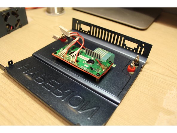
    • The top faceplate can now be separated from the lower charger assembly.

    • Be sure to separate the two parts slowly, checking for snagged wires and other hazards that could cause damage to the charger.

    • Inside you'll find:

    • PIC24HJ128GP310 16-bit Microcontroller

    • PIC ICSP Programming Pins (6 Pins)

    • KA324AD Quad Operational Amplifiers (4 total)

    • 24LC32A 32K I2C Serial EEPROM

    Good job. David, did you work on squematic ?... Did you find electronic squematic from hyperion?

    Rojoalfa - 回复

终点

2等其他人完成本指南。

David Hoyt

于04/09/10注册

4,023 声望

创作了43篇指南

团队

Cal Poly, Team 25-89, Amido Spring 2010 Cal Poly, Team 25-89, Amido Spring 2010 的会员

CPSU-AMIDO-S10S25G89

4 名成员

创作了63篇指南

一条评论

One of my two channels will not charge. The displays are fine everything works on the bad channel and it can be programmed ok. except when the LCD goes into solo CHARGE mode the current load remains at 0.0 and the timer counts off the seconds. The channel works properly in DISCHARGE mode and shows a negative current. I got it for free as a used item. im thinking somebody shorted out the channel when charging.

Does anyone know if the board has fuses and where the fuses are located on the board. I took it apart and didn't see any but they gotta be on there somewhere. If someone knows please drop me an email at jimmynorton7777@gmail.com

thanks

mcorriel - 回复

添加评论

浏览统计数据:

过去 24 小时: 0

过去 7 天: 0

过去 30 天: 6

总计 1,007