简介
My Bauker angle grinder stopped working after a grinding disc came loose.
The fuse in the (UK) plug had not blown, and the RCD breaker had not tripped.
So I needed to dismantle to investigate. This guide explains how to open the grinder and shows where and how the switch is installed and how to access the stator and rotor.
Angle grinders are, of course, powerful and potentially dangerous machines. Please do not connect to mains power until the machine is fully reassembled, and then take precautions when testing.
-
-
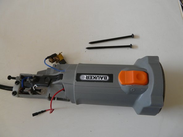
Remove any disc and unscrew the inner and outer flanges. Release the guard clamping lever, and remove the guard completely. You may need loosen the screw at the back of the guard clamp. You should now have a bare machine as shown.
-
-
-
The rear cover can now be pulled off easily. At least this worked for me. The cable shield at the back was quite loose and moved without resistance.
-
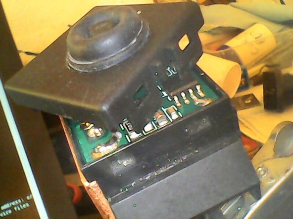
If you zoom in on the image, you can see the yellow safety critical capacitor. Next to its leads are two grey plastic clips that hold the switch assembly. these are the clips that we will need to release later.
-
The capacitor leads and the blue and red leads are connected to the switch output terminals which are behind a black shield so are not easily seen in this view.
-
-
-
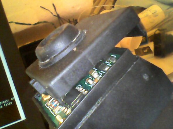
Turn over to reveal the screws retaining the mains inputs. Nearest to the camera is the brown live (phase) wire.
-
The blue neutral terminal is hidden by the black switch activation rod. This runs from the outer orange button (unfortunately clipped out of this picture by the ifixit software) down the length of the casing, zigzagging over the terminal, and then at right angles directly down to operate the switch push button.
-
The rod has a hole over the neutral screw terminal to allow access.
-
Unscrew both terminals. You may need a set of tweezers or long nose pliers to remove the screw under the black rod. The wires have crimp spade ends to match the screws. There should be no need to remove the cable clamp.
-
-
-
Turn the grinder over again, and carefully lift up the capacitor as shown with a any suitable tool to hand: a small flat bladed screw driver is fine.
-
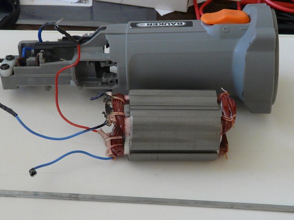
In addition to the two capacitor leads, there are what I take to be red and blue stator leads. As normal on such tools, it is a universal motor with 2 simple stator windings and a more complex rotor with brushes. The brushes are at the top and bottom, and can be inspected at this point.
-
You might need to change or service the brushes at this point, but that is not covered here.
-
Remove the red and blue stator wires from the switch next to the capcitor leads. Use long nose pliers to pull off the crimp connectors: this needs a bit of force, so be careful and pull directly along the terminal axes. The picture shows the blue wire disconnected.
-
Examine the switch and note how the black rod engages with the push button.
-
Notice that the switch has what seems to be a copper heatsink on the side nearest the blue lead.
-
The switch is now held only by the two grey plastic clips.
-
Insert suitable spacers between the body of the switch and the clips. I cut a wooden cocktail stick in half, and inserted the sharp ends behind the clips and tapped the pieces until the clips were just clear of the switch.
-
-
-
At this point you can turn over the grinder and tap out the switch. But the black rod is in the way. I just used a length of wooden dowelling which fitted past the rod and tapped with a rubber hammer.
-
Once the switch is past the clips, you will need to remove the spacers, in my case, the two cocktail stick parts. Otherwise they will be in the way.
-
Now you can simply push or tap until the switch comes out as shown.
-
-
-
-
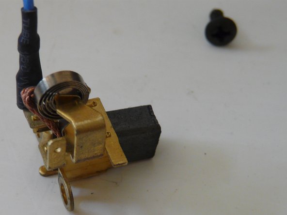
The switch with the push button that engages with the black rod is shown here. One of the brush connections can also be seen in the background in this picture.
-
The heatsink is clear. I unscrewed the copper plate and found some white heatsink compound below against what may have been an aluminium plate
-
I had not encountered a heatsink built into a switch before, so I tried to take the switch apart. I could remove the top cover, but the flexible dome resisted all attempts to remove it, but it is possible to see a circuit board inside. The fuzzy pictures through the crack were taken with a boroscope.
-
The switch seemed to be open circuit on the neutral side, so I looked for replacements. This was before I realised that it was an active circuit. The only candidates that I found seemed to be ordinary passive components..
-
-
-
The picture shows the markings. It seems to be a JIABEN FA2-5F-1108X, whatever that may be. Can anyone through more light on this, or find a datasheet? Perhaps if I could read chinese it would be easy.
-
What is its function beyond a passive switch?
-
With the help of Google translate, I do now have some information. It offers restart protection when the power supply is interrupted and more. It seems to satisfy EN60947.
-
-
-
At this point, all the connections to the brushes and stator windings are exposed, so it is possible to check with a multimeter
-
Checking the stator windings and basic brush continuity is easy. To check the rotor fully, you really need to rotate the motor. It is possible to do that from the rear. There are teeth at the rear of the commutator which you can push with a small screwdriver. But next I outline how to remove the front gearbox: it is straight forward.
-
In my case, I found that one of the stator windings was open circuit. Eventually with a bright light and magnifying spectacles, I discovered the the lead just inside the casing was damaged and had clearly come in contact with the commutator. How did that happen? There should be some way to keep it clear.
-
-
-
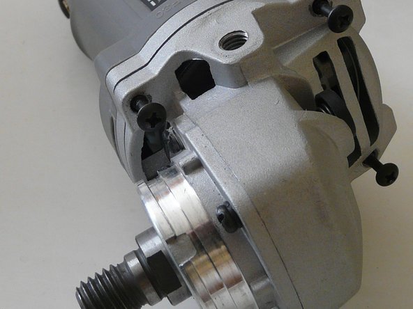
There are 4 obvious screws: 3 can be seen in the photograph. I used a PH2 screwdriver to remove them.
-
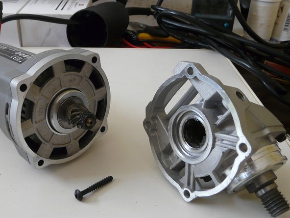
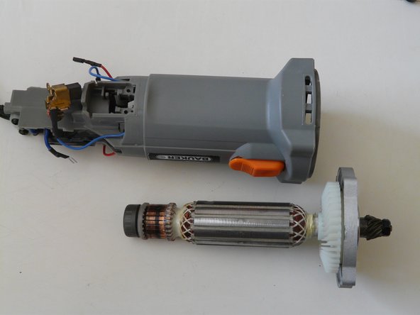
The front drive section can now be removed as shown.
-
-
-
If you need to loosen the front bearing plate, there is a screw driver slot as shown.
-
Even without releasing this plate, it is now possible to rotate the motor shaft although it is greasy so use pliers or a spanner on the front nut.
-
To access the rotor and stator, it is necessary to remove the brushes.
-
-
-
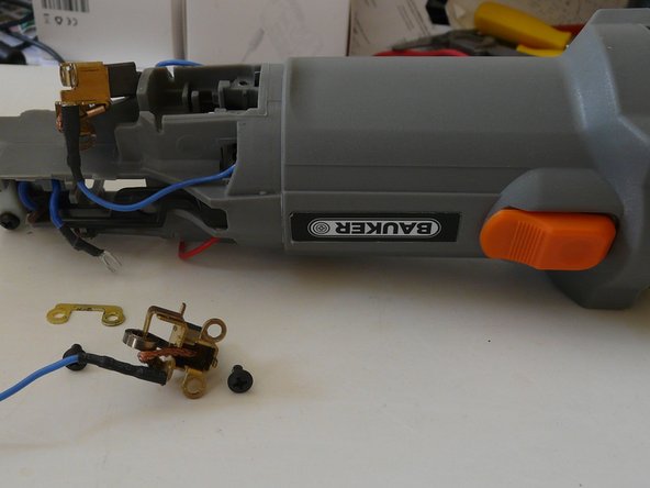
The brushes are each held by two PH2 screws: there is a picture in the next step. Unscrew them and carefully remove taking care not to disturb the springs.
-
There is a washer plate with the two screw holes which is best removed to avoid loss. One is shown in the third picture.
-
Obviously it is a good idea to check the brushes and renew if needed.
-
-
-
The two screws holding one of the brushes are shown.
-
Once the brushes have been removed, the rotor can be withdrawn. Be careful when easing the rear bearing out of its recess. Use a small screw driver to guide the withdrawal.
-
-
-
You probably only need to remove the stator if it has a fault. In my case one of the leads was broken close to a coil.
-
First remove the front cover: it simply pulls out.
-
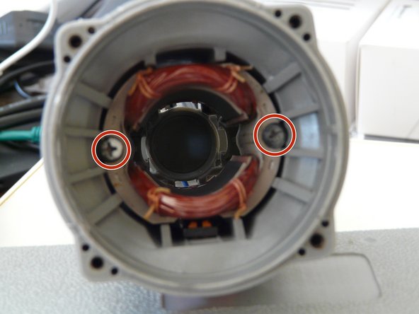
The two screws holding the stator can now been seen. As always they seem to be PH2.
-
Unscrew them: they may be quite tight.
-
-
-
To remove the stator from the case, it will almost certainly be necessary to use some sort of tool. It might be possible to use some sort of hook, but I decided to try to tap it out from the rear.
-
However it is vital only to apply taps/force to the laminations away from the winding. The case has some small slots where the brushes fit, and those are directly above sections of laminations.
-
I improvised a simple tool by cutting a short section of an almost rectangular rod from an old ventian blind mechanism. That rod has just the right cross section. The picture shows it inserted into one of the holes and resting against the laminations.
-
It only needed a few light taps each side to drive out the stator.
-
The second picture shows the stator removed from the case, and part of the rod in front. The picture has had to be cropped so only a portion is visible.
-
The stator had suffered damage: most obviously the severed lead, but also blackening in the adjacent area and on the other lead. But the coil was intact, and the lead could be repaired
-
-
-
To re-install the stator involves threading the right leads through the correct holes. I found this difficult.
-
The way that I did this was by tying pieces of thin string to the leads, and threading those first. But it was then difficult to manipulate the crimp connectors through because the strings had to be tied above them. It took some patience with a variety of probes to achieve this. Perhaps you can find a better way?
-
Thr grinder is nominally 750 W, but the UK mains plug had a 13A fuse. I suggest instead a 5A or even 3A fuse.
-
The body of the grinder is plastic: I am not sure how durable that is. At least one screw thread was somewhat damaged. Almost all of the screws are self tapping: it might be possible to insert small strands of thermal plastic to restore grip.
-


To reassemble your device, follow these instructions in reverse order.
To reassemble your device, follow these instructions in reverse order.
2条评论
Kenapa gurinda berbunyi kasar dan tidak berputar?
Well, if the translation is correct you are saying that the motor does not rotate and there is a rough noise.
That sounds unlikely, so perhaps that means that the rotation is slow, otherwise I am not sure whether there would be any noise, although I guess that there could be some vibration. It all sounds dangerous, so don't try again until you have followed the guide and disassembled to see what is wrong.
Why might that happen? Who knows, but the very first thing is to check the brushes. If they are OK, presumably it could be a broken gear box.
Once you have disassembled that far, you can see whether the gear box turns freely. Next could be the bearings. I can't think of anything else obvious unless the grinder has overheated and distorted the plastic body out of shape.