跳转到主内容

Zenbre SoundBank Z3 Control Interface Circuit Board Replacement

你所需要的

  1. Zenbre SoundBank Z3 Control Interface Circuit Board Replacement, Bottom Cover: 步骤 1 中的图像 1,2 Zenbre SoundBank Z3 Control Interface Circuit Board Replacement, Bottom Cover: 步骤 1 中的图像 2,2
    • Power off the SoundBank Z3.

    • Turn over the device.

    • Peel the silicone feet up to remove.

    • No extra adhesive is needed to reapply the feet as long as the sticky side is not touched.

  2. Zenbre SoundBank Z3 Control Interface Circuit Board Replacement: 步骤 2 中的图像 1,1
    • Remove all eight of the 11 mm Phillips screws from the bottom of the device.

  3. Zenbre SoundBank Z3 Control Interface Circuit Board Replacement: 步骤 3 中的图像 1,2 Zenbre SoundBank Z3 Control Interface Circuit Board Replacement: 步骤 3 中的图像 2,2
    • Remove the bottom panel speaker using an iFixit opening tool.

  4. Zenbre SoundBank Z3 Control Interface Circuit Board Replacement, Motherboard Cover: 步骤 4 中的图像 1,3 Zenbre SoundBank Z3 Control Interface Circuit Board Replacement, Motherboard Cover: 步骤 4 中的图像 2,3 Zenbre SoundBank Z3 Control Interface Circuit Board Replacement, Motherboard Cover: 步骤 4 中的图像 3,3
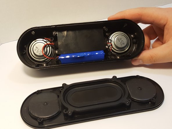
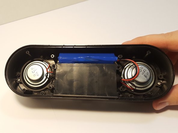
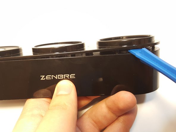
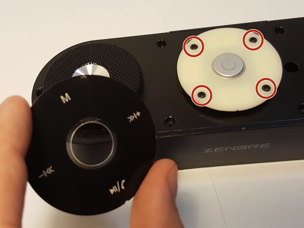
    • Remove the four 4.5 mm silver Phillips screws that secure the plastic panel covering the motherboard.

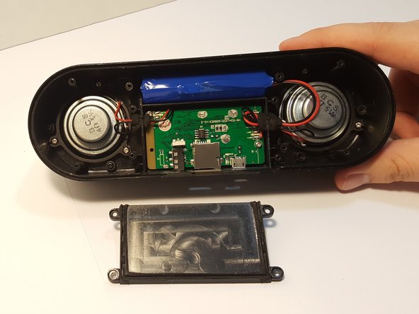
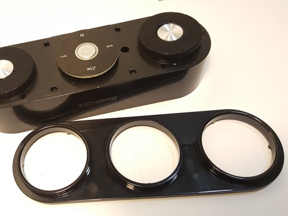
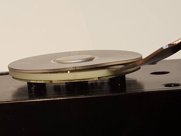
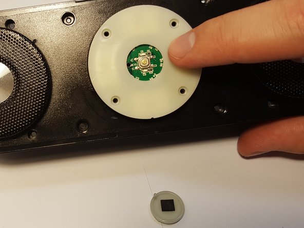
    • Remove the plastic panel.

  5. Zenbre SoundBank Z3 Control Interface Circuit Board Replacement, Battery: 步骤 5 中的图像 1,2 Zenbre SoundBank Z3 Control Interface Circuit Board Replacement, Battery: 步骤 5 中的图像 2,2
    • Remove the battery from the holder. It may be difficult the first time.

    • Use a spudger between the battery and speaker wall to loosen it from its surroundings.

    • If the battery is punctured, leaking, or bloated/puffy, it may be hazardous and should be properly disposed of.

  6. Zenbre SoundBank Z3 Control Interface Circuit Board Replacement: 步骤 6 中的图像 1,2 Zenbre SoundBank Z3 Control Interface Circuit Board Replacement: 步骤 6 中的图像 2,2
    • Remove the pressure-fitted foam from the slot by hand.

    • Unravel and remove foam from the wires.

    • When reassembling, the foam can be re-wrapped if care is taken when handling it.

  7. Zenbre SoundBank Z3 Control Interface Circuit Board Replacement: 步骤 7 中的图像 1,1
    • Using a soldering iron, remove the leads, separating the battery from motherboard.

    • Follow this guide to help you remove the wires from the motherboard if you are unfamiliar with soldering.

  8. Zenbre SoundBank Z3 Control Interface Circuit Board Replacement, Speakers: 步骤 8 中的图像 1,2 Zenbre SoundBank Z3 Control Interface Circuit Board Replacement, Speakers: 步骤 8 中的图像 2,2
    • Remove the three screws that are holding the speaker down.

    • Be careful not to rip out the speaker while taking out the screws.

  9. Zenbre SoundBank Z3 Control Interface Circuit Board Replacement: 步骤 9 中的图像 1,2 Zenbre SoundBank Z3 Control Interface Circuit Board Replacement: 步骤 9 中的图像 2,2
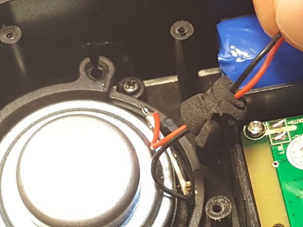
    • Desolder the speaker joints from the motherboard. Follow this How To Solder guide for help with desoldering.

  10. Zenbre SoundBank Z3 Control Interface Circuit Board Replacement: 步骤 10 中的图像 1,2 Zenbre SoundBank Z3 Control Interface Circuit Board Replacement: 步骤 10 中的图像 2,2
    • Remove the speaker from the motherboard.

    • Remove the speaker ring.

    • Be careful not to remove other components in the speaker.

    • Repeat Steps 5-7 with the other speaker.

  11. Zenbre SoundBank Z3 Control Interface Circuit Board Replacement, Control Interface Circuit Board: 步骤 11 中的图像 1,2 Zenbre SoundBank Z3 Control Interface Circuit Board Replacement, Control Interface Circuit Board: 步骤 11 中的图像 2,2
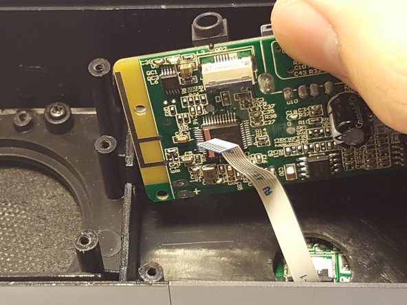
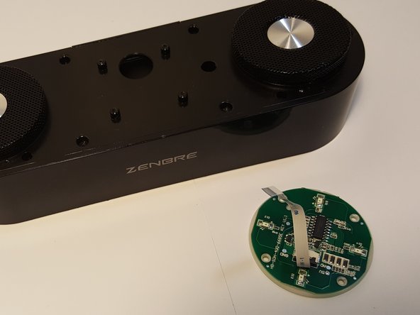
    • Remove the two 4.5 mm Phillips silver screws holding down the motherboard.

    • Note the ribbon that connects the motherboard to the control interface. Be careful with this while removing the motherboard, as it can tear easily.

    • Lift the motherboard out of its housing.

  12. Zenbre SoundBank Z3 Control Interface Circuit Board Replacement: 步骤 12 中的图像 1,2 Zenbre SoundBank Z3 Control Interface Circuit Board Replacement: 步骤 12 中的图像 2,2
    • Use an iFixit opening tool to lift up the ribbon connector.

    • Slide the ribbon cable out of its connector.

  13. Zenbre SoundBank Z3 Control Interface Circuit Board Replacement: 步骤 13 中的图像 1,1
    • Remove the four 4.5 mm Phillips silver screws.

    • Remove the six 7 mm Phillips black screws.

  14. Zenbre SoundBank Z3 Control Interface Circuit Board Replacement: 步骤 14 中的图像 1,3 Zenbre SoundBank Z3 Control Interface Circuit Board Replacement: 步骤 14 中的图像 2,3 Zenbre SoundBank Z3 Control Interface Circuit Board Replacement: 步骤 14 中的图像 3,3
    • Remove the top plastic cover by prying around the edges with an iFixit opening tool.

  15. Zenbre SoundBank Z3 Control Interface Circuit Board Replacement: 步骤 15 中的图像 1,3 Zenbre SoundBank Z3 Control Interface Circuit Board Replacement: 步骤 15 中的图像 2,3 Zenbre SoundBank Z3 Control Interface Circuit Board Replacement: 步骤 15 中的图像 3,3
    • Carefully remove the round black cover of the circuit board by using a spudger to pry it upward.

    • When working with electronics, it's important to choose a tool that is electrostatic discharge (ESD) safe in order to avoid accidental damage to the device. A metal spudger is great when you need serious prying power, but a regular black nylon spudger or a plastic tool should be used whenever possible.

    • Handle the cover plate carefully. Just like with the feet from before, it can be replaced if care is used when handling it.

    • Remove the four screws.

  16. Zenbre SoundBank Z3 Control Interface Circuit Board Replacement: 步骤 16 中的图像 1,2 Zenbre SoundBank Z3 Control Interface Circuit Board Replacement: 步骤 16 中的图像 2,2
    • Pick up the center power button and remove it. Place it in a safe location.

    • When you pick up the power button, the board will come right off. Be sure not to lose it.

  17. Zenbre SoundBank Z3 Control Interface Circuit Board Replacement: 步骤 17 中的图像 1,3 Zenbre SoundBank Z3 Control Interface Circuit Board Replacement: 步骤 17 中的图像 2,3 Zenbre SoundBank Z3 Control Interface Circuit Board Replacement: 步骤 17 中的图像 3,3
    • Remove these four 7 mm black screws.

    • This will free the circuit board, which can now be lifted away from the housing.

    • If you wish to remove the ribbon here, use the same method used to remove the ribbon from the motherboard earlier in this guide.

结论

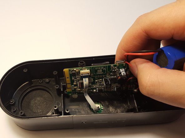
To reassemble your device, follow these instructions in reverse order.

另外一个人完成了本指南。

Cherian Thomas

于03/25/16注册

334 声望

创作了5篇指南

团队

UMass Dartmouth, Team 3-2, Bhusal Spring 2016 UMass Dartmouth, Team 3-2, Bhusal Spring 2016 的会员

UMASSD-BHUSAL-S16S3G2

5 名成员

创作了8篇指南

0条评论

添加评论

浏览统计数据:

过去 24 小时: 0

过去 7 天: 0

过去 30 天: 1

总计 327