跳转到主内容

Connecting Cables to the Motherboard

你所需要的

  1. Connecting Cables to the Motherboard, Connecting Cables to the Motherboard: 步骤 1 中的图像 1,2 Connecting Cables to the Motherboard, Connecting Cables to the Motherboard: 步骤 1 中的图像 2,2
    • Red- Optional ATX Connector

    • Orange- CPU Fan 1

    • Yellow- CPU Fan 2

    • Green- Main ATX Connectors

    • Light Blue- GPU

    • Blue- Panel Connectors

    • Pink- USB Connectors

    • Black- HD Audio

  2. Connecting Cables to the Motherboard, Optional ATX Connector: 步骤 2 中的图像 1,2 Connecting Cables to the Motherboard, Optional ATX Connector: 步骤 2 中的图像 2,2
    • Connect the two separate six-pin segments to six pins each on the 12-pin PCIE port.

  3. Connecting Cables to the Motherboard, CPU Fan 1: 步骤 3 中的图像 1,2 Connecting Cables to the Motherboard, CPU Fan 1: 步骤 3 中的图像 2,2
    • Connect the four pin segment to the four pin PCEI connector labeled "CPUFAN1."

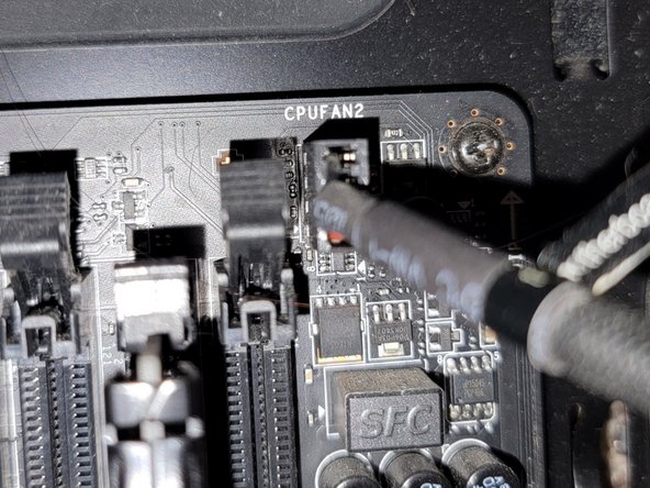
  4. Connecting Cables to the Motherboard, CPU Fan 2: 步骤 4 中的图像 1,2 Connecting Cables to the Motherboard, CPU Fan 2: 步骤 4 中的图像 2,2
    • Connect the four pin segment to the four pin PCIE port labeled "CPUFAN2."

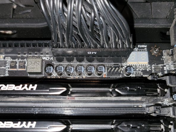
  5. Connecting Cables to the Motherboard, Main ATX Connector: 步骤 5 中的图像 1,2 Connecting Cables to the Motherboard, Main ATX Connector: 步骤 5 中的图像 2,2
    • Connect the 24 pin segment to the 24 pin PCIE port.

  6. Connecting Cables to the Motherboard, GPU: 步骤 6 中的图像 1,2 Connecting Cables to the Motherboard, GPU: 步骤 6 中的图像 2,2
    • Connect both of the separate eight pin segments to each of the eight pin PCIE ports on the graphics card.

  7. Connecting Cables to the Motherboard, Panel Connectors (Part 1): 步骤 7 中的图像 1,3 Connecting Cables to the Motherboard, Panel Connectors (Part 1): 步骤 7 中的图像 2,3 Connecting Cables to the Motherboard, Panel Connectors (Part 1): 步骤 7 中的图像 3,3
    • This PCIE port consists of eight pins, two rows of four.

    • Connect the "Power LED+" pin to the pin at the top right corner.

    • Connect the "Power LED-" segment to the pin next to the "Power LED+" segment in the top row.

    • Connect the "Power SW" segment to the two pins on the left side of the top row of pins.

  8. Connecting Cables to the Motherboard, Panel Connectors (Part 2): 步骤 8 中的图像 1,3 Connecting Cables to the Motherboard, Panel Connectors (Part 2): 步骤 8 中的图像 2,3 Connecting Cables to the Motherboard, Panel Connectors (Part 2): 步骤 8 中的图像 3,3
    • Connect the "HDD LED" segment to the two pins on the right side of the bottom row of pins.

    • Connect the "Reset SW" segment to the two pins on the left side of the bottom row of pins.

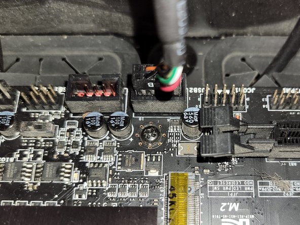
  9. Connecting Cables to the Motherboard, USB Connector: 步骤 9 中的图像 1,2 Connecting Cables to the Motherboard, USB Connector: 步骤 9 中的图像 2,2
    • Connect the nine pin segment to the nine pin PCIE port.

  10. Connecting Cables to the Motherboard, HD Audio: 步骤 10 中的图像 1,2 Connecting Cables to the Motherboard, HD Audio: 步骤 10 中的图像 2,2
    • Connect the nine pin segment to the nine pin PCIE port.

结论

To disconnect the cable ties, follow these directions in reverse order.

Grace Parsekian

于12/05/23注册

181 声望

撰写一个指南

0条评论

添加评论

浏览统计数据:

过去 24 小时: 9

过去 7 天: 82

过去 30 天: 441

总计 1,436