当前版本的文档还未经巡查,您可以查看最新的已查核版本 。
Remove the plastic subsection by prying it with your fingers.
Note: It may be helpful to pry from the bottom of the camera with the battery door open.
The wrist strap attachment behind the subsection will come loose and may fall out.
Flip the camera upside down.
Remove the following screws with a #00 Phillips screwdriver.
One black 3.4 mm Phillips screw.
One silver 3.4 mm Phillips screw.
NOTE: Using your fingernails may help in removal.
Place the camera on the side opposite of the wrist strap handle.
Then begin to pry the casing apart with both hands by applying pressure to the top and bottom of the camera.
Remove the small metal plate underneath the plastic covering and set aside. (It should be loosely attached)
Note: A rubber foam washer that separates the lens from the casing will fall off when the case is removed. Be sure to store it safely.
Note: When reassembling ensure the back plate screw tabs are over the wrist strap attachment and the front plate screw tabs go under orange casing.
Flip the camera right side up.
Remove the silver 3.5 mm screw (located on top of the camera) with a #00 Phillips screwdriver.
Grip the corner of the A/V digital port and pull up and outward.
Note: You may encounter some resistance when removing the A/V digital port. Apply enough pressure in order to remove this piece.
Note: When reassembling, snap the corner plate back into its position. (Push down and inward)
Slide the LCD screen to the left of the camera and then gently pull the LCD screen away from the camera.
Note: Hold the screen and frame together.
Be sure to align the screen properly.
Be gentile and do not tear the ribbon connector for the LCD screen to camera.
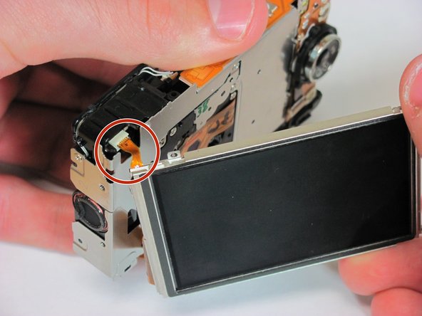
Locate the two ribbons connected to the camera and the LCD screen. (One is red and small and the other is wide and orange)
Remove the top left red ribbon by gripping the connector on the camera and sliding it straight out.
Remove the side orange ribbon by gripping the connector on the camera and sliding it straight out.
Note: It may be helpful to use tweezers when removing the connectors. (Pay close attention to how the ribbons are disconnected as this will help in replacing the screen later)
Note: When reassembling, use tweezers to reconnect the small red connector on the top left of the screen.
Place the camera forward so that the LCD screen side is facing up.
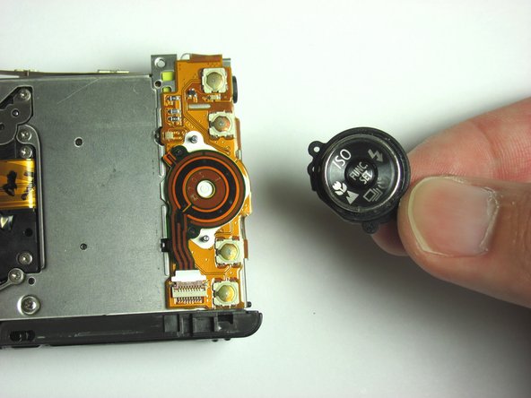
Remove the circular plastic button from the back of the camera.
Be sure to set the circular plastic button aside.
Leave the camera facing forward.
Grab the round orange and black stripped connector as pictured.
Then rotate the connector upward and pull the ribbon out.
Place the camera backward so that the lens is facing up.
Disconnect the ribbon that attaches to the motherboard by rotating the connector upwards.
Pull the ribbon out of the ZIF connector.
Place the camera backward so that the lens is facing up.
Disconnect the ribbon at the bottom of the main board by flipping up the brown ZIF connector and sliding the ribbon out.
Note: Tweezers are recommended to perform this step.
Remove the right most square connector at the bottom of the camera by flipping up the connector with two fingers until it detaches.
Locate and remove the white rubber cover on the microphone.
Note: Be sure not to lose the white rubber cover for the microphone.
Leave the camera facing backward so that the lens is facing up.
Remove the square connector at the top of the motherboard by grabbing the connector with two fingers and pulling up until it detaches.
Refer to the picture for correct removal.
Leave the camera facing backward so that the lens is facing up.
Flip up the ZIF locking mechanism using a paperclip
Note: Place the paper clip in the holes on either end of the ZIF locking mechanism.
Use the paperclip to pull the ribbon cable from the ZIF socket.
Leave the camera facing backward so that the lens is facing up.
Remove the two flat silver 3.46 mm Phillips screws with a #00 Phillips screwdriver connecting the motherboard to the frame of the camera.
Leave the camera facing backward so that the lens is facing up.
Pull the motherboard out by lifting it up on the left side about a 1/2 inch from the case and then slide it to the left.
Note: When reassembling, make sure the ZIF connectors are not covered by motherboard.
Caution: When removing the motherboard, pay special attention to the battery door detection switch or you may break the plastic nib.
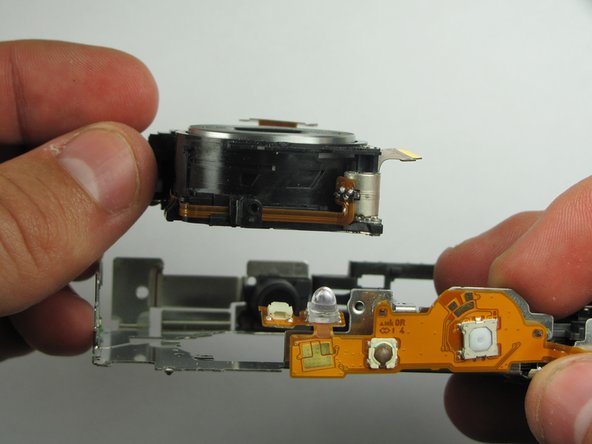
Place the camera facing forward so that the LCD screen side is facing up.
Remove the four 3.2 mm Phillips screws with a #00 Phillips screwdriver.
Note: The screws are located around the edges connecting the lens to the casing.
Do not remove the top right Phillips screw because the lens gears may fall out.
嵌入本指南
选择一个尺寸并复制下面的代码,将本指南作为一个小插件嵌入到你的网站/论坛中。
单个步骤
完整指南
小——600像素
中——800像素
大——1200像素
预览