本指南有最近更改,您可查看未经巡查的最新版本。
简介
This guide will show step by step how to replace the PCB flashboard following damage or exposure to the capacitor and/or the circuit itself.
你所需要的
-
-
Remove two 6.8 mm JIS #000 screws on the right side.
-
Remove six 5.3 mm JIS #000 screws on the bottom.
-
Remove two 5.3 mm JIS #000 screws on either side of the viewfinder.
-
-
-
-
Disconnect the ribbon connector on the upper right side of the motherboard.
-
Pull back the foam on the connector on the far right side of the motherboard.
-
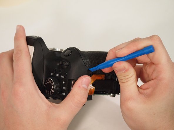
Flip up the tab on the connector and remove the cable.
-
-
-
Warning - Failure to follow steps may lead in damage or injury from electrical shock. Before removing or touching the PCB board, the Capacitor needs to be checked for voltage. This device is the black cylinder on the camera. Place a voltmeter in parallel with the capacitor. If a charge is detected, make sure battery is removed from the device.
-
Furthermore, The positive pin is connected to the positive terminal and negative to the negative terminal. Then switch the setting of the multi meter to ADC for direct current amperage. .
-
-
-
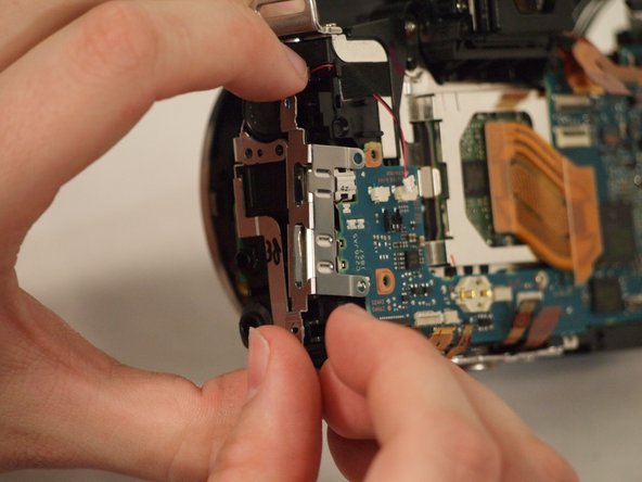
Caution - Using a magnetic tipped screw driver may cause damage to the board. ordinary bits are preferred. There are 3 screws that must be removed in order to disconnect the board.
-
Furthermore, there are several ribbon connectors that need to be removed. Marked in red.
-
Remove the four wire connectors on the front.
-
Remove the two wire connectors on the back.
-


To reassemble your device, follow these instructions in reverse order.
To reassemble your device, follow these instructions in reverse order.
另外一个人完成了本指南。
团队

University of Memphis, Team S2-G1, Kim Spring 2018 University of Memphis, Team S2-G1, Kim Spring 2018 的会员
UM-KIM-S18S2G1
3 名成员
创作了11篇指南