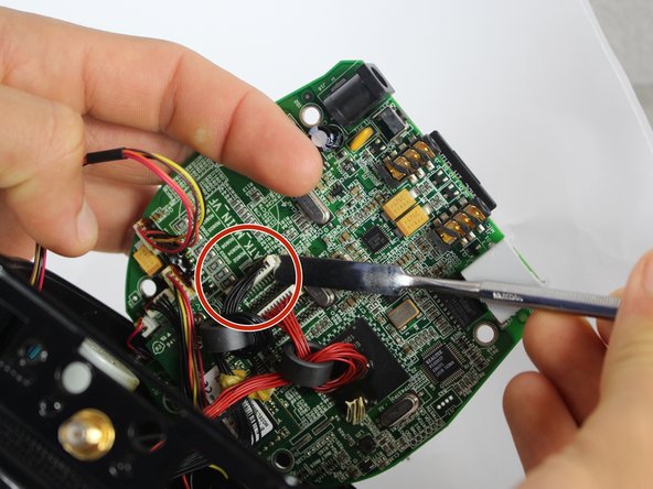
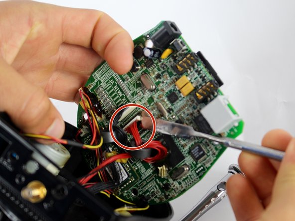
跳转到主内容

Astak Mole Camera Head Replacement

你所需要的

  1. Astak Mole Camera Head Replacement, Lower Case: 步骤 1 中的图像 1,1
    • Remove the four bottom tabs in order to access the bottom screws.

  2. Astak Mole Camera Head Replacement: 步骤 2 中的图像 1,1
    • Remove all four 14 mm Phillips #1 screws.

  3. Astak Mole Camera Head Replacement: 步骤 3 中的图像 1,1
    • Remove the SD card.

  4. Astak Mole Camera Head Replacement: 步骤 4 中的图像 1,1
    • Pry up the motherboard on the four points using a spudger.

    • The regular black nylon spudger should be used whenever possible, especially around sensitive internal components.

  5. Astak Mole Camera Head Replacement: 步骤 5 中的图像 1,1
    • Gently pull back the motherboard to expose many of the component's wired connections.

  6. Astak Mole Camera Head Replacement, Camera Head: 步骤 6 中的图像 1,1
    • Unscrew the three screws connecting the base to the camera head with the PH1 size Phillips head bit.

    • Screw measurements: Length=7.0mm.

    • The third screw can be exposed by rotating the camera head.

    • Do not force the camera head farther than it will allow you.

  7. Astak Mole Camera Head Replacement: 步骤 7 中的图像 1,1
    • Unscrew indicated Phillips head screws using the PH1 Phillips head bit to free wires.

    • Screw measurements: Length=3.5mm

  8. Astak Mole Camera Head Replacement: 步骤 8 中的图像 1,3 Astak Mole Camera Head Replacement: 步骤 8 中的图像 2,3 Astak Mole Camera Head Replacement: 步骤 8 中的图像 3,3
    • Separate the three indicated outputs from the motherboard with metal spudger.

    • There is electrical adhesive on the output. This can be easily separated with the metal spudger.

    • The regular black nylon spudger should be used whenever possible, especially around sensitive internal components.

  9. Astak Mole Camera Head Replacement: 步骤 9 中的图像 1,1
    • Separate the wire from CPU by cutting adhesive with metal spudger.

    • It is advised to reapply adhesive to wired connections during reassembly, and to re-attach wires to CPU to prevent disconnection and loose wires inside device.

    • Be careful not to damage the CPU in the process. This is not a wired connection.

结论

To reassemble your device, follow these instructions in reverse order.

Bryan

于09/15/16注册

104 声望

撰写一个指南

团队

USF Tampa, Team 2-2, Blackwell Fall 2016 USF Tampa, Team 2-2, Blackwell Fall 2016 的会员

USFT-BLACKWELL-F16S2G2

4 名成员

创作了12篇指南

0条评论

添加评论

浏览统计数据:

过去 24 小时: 0

过去 7 天: 4

过去 30 天: 8

总计 464