There are lots of cordless phones that meet the DECT specification, all different, especially in ways that are possibly outside of the DECT spec. such as the battery charging circuit. I'm an electronic design engineer and very experienced in the field. I got so sick of my Panasonic cordless phones going through NiMH batteries every couple of years when, if charged properly, they should last much longer, (I fitted a 10 cell pack of Panasonic AA NiMH batteries, (date coded 0405), as 12V backup in my burglar alarm system, maintained by a precision CVCI float charger and on load testing them, they're still good after nearly 19 years service).
From my investigations I suspect that the Panasonic system is a switch on/switch off bulk charging system which continually unnecessarily cycles the batteries and thus dramatically reduces their life. I suspect this is compounded by too high a 'charged' voltage detection that exacerbates the problem by overcharging the cells. To solve both of these problems needs a two-stage solution:
1) Firstly to install a system compatible precision float charger which can maintain the battery level at a constant 'fully charged' level by strict control of the charger current and a precise limit on the upper battery voltage to eliminate over charging.
2) This would then make the crude Panasonic 'switch on','switch off' charging system redundant and it can be disabled to the 'charging' condition to fully implement a constant voltage/constant current (CVCI) float charger that does not continually cycle the cells.
The following mod. implements part 1) of the solution and eliminates any over-charging with a system compatible charger solution. After a period of assessment, part 2) can be investigated to eliminate any residual unnecessary battery cycling.
So, back to my Panasonic DECT cordless phones, (KX-TCD220E):
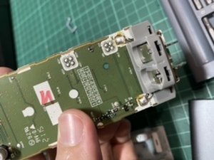
When I took the cradle of a slave handset apart I was surprised to find that the charger circuit is very crude and possibly at least partially the cause of the prematurely dying NiMH batteries - it consists of a 6V AC 0.5A transformer + rectifier + smoothing/reservoir capacitor in the wall adaptor, and all that's in the cradle is a couple of 22 Ohm parallel connected SMD resistors in series with a Schottky blocking diode straight to the cradle battery contacts & that's it. In other words just an 11 Ohm resistor straight to the handset batteries via a Schottky blocking diode. I wondered why the batteries got rather warm to the touch & all my phones are equally problematic. I couldn't believe a firm like Panasonic would be guilty of such a bodge, and certainly in the handset there appears to be some sort of control on one of the input battery connections, but what algorithm it follows I don't know, but from all the problems it undoubtedly does seem to overcharge the batteries. Oh, and BTW, beware of the polarity - on mine, Panasonic have managed to opt for -ve to the centre connector making it out of step with most other adaptors...
Anyway, to cut a long story short it was clear that nothing could be done to the Panasonic charge control for the moment, so I turned my attention to the charger itself and I bought some nice very cheap CVCI adjustable voltage buck switching regulator modules for next to nothing from China, (see images), which would produce near enough the correct charging parameters for NiMH batteries and incorporated them in the slave and base station cradles and carefully adjusted them, (in place of the existing charger 22 Ohm dropper resistors which should be shorted out when the mod. is complete), to fall back to a very low maintenance charge once a full charge voltage of 2.86 volts for the series AAA battery pair had been reached, (i.e. when the batteries are fully charged), so now there's no possibility of battery cooking as the module efficiently limits the charger voltage and current available to safe levels. The whole system still charges, indicates and works 100% normally - the additional module simply removes any possibility of overcharge by replacing the 22 Ohm dropper resistors with a CVCI charger module. The handsets are untouched and remain DECT compatible. If you do this modification I'd advise changing the batteries at the same time as the existing ones will not be in good condition.
Nothing kills ANY battery quicker than pouring full charge current into them when they are fully charged which is what seemed to be happening, and , of course, all batteries have a limit on the number of charge/discharge cycles they can achieve. The next step will be to investigate disabling the Panasonic charger control to see what effect that will have on the system indications.
PS. Just to emphasise, this step 1) is designed to allow any existing Panasonic battery charge control to do its thing, (whatever that is in my particular KX-TCD220E setup - let me know if you have any idea), but to prevent it overcharging the battery unnecessarily by carefully regulating the available charger output only and it seems to work perfectly on my two base units and six handsets. Only time will tell if it's effective or not on its own as the system can possibly still cycle the batteries. I've come across many cases like this based on the misconception that NiMH and NiCd batteries can be safely charged with a constant current irrespective of the state of charge which simply isn't true - all battery chemistries will be damaged by unnecessary overcharge, (although some are more sensitive than others...).
I've now had a look at an online workshop manual/handset schematic and nowhere can I find the voltage that the handset cuts off the charge to the handset batteries, just at what voltage it initiates the charge, but as far as I can see, the suggested modification should work OK with the Panasonic firmware control, which becomes essentially redundant as a result of this mod.
PPS. All of the Schottky blocking diodes in my chargers were OK, but there is no harm in upgrading them to 3 Amp. devices, apart from a possible minor increase in reverse leakage.
Panasonic Cordless Phone System type KX-TCD220E Slave Handset Charger Modifications.
The following modification is specific to my cordless phone set, (KX-TCD220E), but should be relevant for other Panasonic variants. Look at all the complaints of these phones unnecessarily killing re-chargeable NiMH batteries and know that big names don’t always get it right and Panasonic are no exception. This should be suitable for someone with reasonable knowledge and soldering skills.
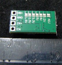
Existing Slave Charger circuit Variable CVCI* module (Aliexpress)
Modified Slave Cradle Charger Assembly (See separate instruction for base unit modification):
1. Prepare the CVCI control module by bridging the ‘5V’ and ‘Adj’ voltage setting points on the rear of the module pcb with a globule of solder as shown. This will give optimum fine control of the module output voltage to 3.2 Volts by adjustment of the miniature CVCI unit voltage adjustment potentiometer. See setting up instructions and module photographs.
2. Unplug the DC plug from the cradle assembly socket and unscrew the two cradle assembly securing screws. Separate the two parts of the cradle assembly. Insulate rear of power socket J1 with insulating tape patch to prevent any contact with the charger module.
3. Break the pcb connection to the Schottky diode anode by cutting a small section out of the copper track immediately behind the diode anode. Unclip the PCB from the cradle. Solder three c. 4” insulated wires to module connections Vo+, In+ and Gnd and mount module on sticky pad in any clear position. (See photograph for suggested position).
4. Connect the CVCI module Vin+/In+ connection to the cradle power socket +ve (outer) connection.
5. Connect the CVCI module Vo+ connection to the isolated Schottky diode anode connection.
6. Connect the CVCI module GND connection to the cradle power socket negative (centre pin) connection. (The module ‘EN’ connection is left unconnected). Clip the PCB back into the cradle.
7. Important! - By-pass the 22R resistors on the cradle board by connection a wire between the Schottky diode cathode connection and the cradle PCB +ve handset contact, (or simply connect a short piece of wire across one of the 22R parallel connected resistors).
Optional ‘Power On’ indication upgrade: Drill a 5mm hole in the charger cradle midway between the centre of the ‘Panasonic’ legend and the bottom of the cradle and insert a 5mm green LED, secured on the inside by a blob of hot-melt adhesive. Wire the LED anode via a 100 Ohm ¼ W resistor to the Schottky diode anode/CVCI module Vo+, (not the handset contacts) and the cathode end to the power socket –ve.
Setting up (Must be accurate for best results).
1. Check all connections, remove any handset and connect a temporary >2 watt 10 Ohm ‘dummy load’ resistor across the two external battery connector spring terminals and plug the adaptor DC plug into the cradle socket.
2. Connect an accurate digital test meter across the above load resistor, power up the system and adjust the output control of the CVCI module to give an exact indicated voltage of 3.2 volts across the 10 Ohm dummy load resistor.
3. Remove the dummy load resistor, reassemble the cradle and that’s it! Don’t forget to replace the old AAA batteries – I suggest Ansmann 1100mAh AAA rechargeable NiMh batteries for best performance.
N.B. – Always leave the handset sitting in its powered charger when not in use. Following this modification the batteries will charge as fast or faster than before, but will no longer over-charge, the handset will run cooler, (especially as the modification is much more efficient than the crude ‘dropper resistor’ original system), and the batteries should last much longer.
The modification can also be applied to the Base Unit as follows, even though its power circuit is more complex:
Panasonic Cordless Phone System type KX-TCD220E Base Unit Charger Modifications.
1. Prepare the CVCI control module exactly as in 1 above, including soldering the three wire tails, but in this case, solder a 1A 40V Schottky diode, (e.g. 1N5819), in the Vo+ pcb hole, (anode to the pcb), and connect the Vo+ tail to the diode cathode instead of directly to the board.
2. Unplug the base unit DC power and landline plugs & remove the four case screws on the underside.
3. Unscrew the screw securing the little LED sub-board. This allows the main board to be tilted back for access.
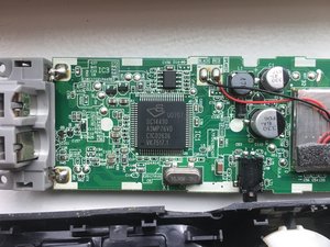
4. Mount the CVCI module on a little sticky pad in a suitable position as before, (see photograph for suggestion, but anywhere that clears the case will do).
5. Unsolder the existing battery +ve wire, (Red in my unit), from the spring battery connector assembly and connect it to the Vin+ tail from the CVCI module – insulate the connection, (which goes to the +ve supply on the main board), with a piece of silicone or heatshrink sleeving. Alternatively the existing red connection can be unsoldered from the main board + connection and a new connection made from the main board + connection to the module Vin+.
6. Connect the module Vo+ connection, (via the 1N5819 diode), to the +ve battery spring terminal on the battery connector assembly. Solder a shorting link across one of the battery charging resistors on the topside of the main board, (i.e. R3 – marked 220 – see photograph below).
If the optional LED ‘Power On’ modification is required then the 5mm hole can be drilled in the case in the same place as above and the LED should be connected with its cathode to the battery assembly –ve connector and the LED anode connected via a 100 Ohm resistor to the Module Vo+ output connection on its pcb, (not the Schottky diode cathode). See pictures below.
The set up is the same procedure as above, (3.2 Volts), with the temporary 10 Ohm 2W resistor connected across the battery spring cradle output terminals, (with no handset installed) and once done, remove the 10 Ohm temporary dummy load, replace the main board, the LED sub-board and the rear cover and don’t forget to replace the handset batteries with new ones!
As a final check that the modification has been done correctly, secure two fine temporary test leads under the battery pair connections in the handset, (charger contacts end), place the handset in the charger cradle and wait for the charging indication to cease. The measured battery voltage on the test leads should then be between 2.86V and 2.88V with new batteries. If it is significantly different then check that you have done the modification and the initial setup correctly. A minor discrepancy can be trimmed out by a small adjustment of the CVCI board pot..
*CVCI module = Constant Voltage/Constant Current very high efficiency precision switch mode voltage buck converter with current limit. Available from Ali Express: https://www.aliexpress.com/item/32801569...
Well it's a couple of months or so since I modified my two base units and six handsets as above and not a single problem to date. It will take several years to prove the effect on battery life, but as the CVCI modules limit the cell charging/running voltage to 1.43 volts per cell, they should last for many years longer than they used to.
All slave and base unit handsets continue to function perfectly as normal.


9条评论
I'd like to add that I've experienced this same problem. The entire set was stored in box for 2 years after using it for about 3 years. When setup again, I found that I could only charge handsets on the base station and none of the three remote chargers would work. It would show "CHARGING" status for 2 or more days and then the batteries would go dead. Purchased new batteries and same.
Purchased a replacement charger and cradle from Panasonic ($30!) and that one works.
I suspected a problem with the cradles, but never believe that all 3 could have gone bad. Now I'll have to investigate them more carefully.
由 Glenn Nelson 完成的
Hi There Folks! I have a set of Panasonic Phones as well, not sure what the model # is. However, I just purchased new batteries too, with no charging happening. What they are doing however is beeping, beep - beep - beep - it never stops....I unplugged the phone and plugged it back in, made no difference both phones are beeping. I have a 3 phone set- but lost one of them so I have the master one and one satellite. Is the Diode Issue a possible cause of this as well? They have been charging for more than 24 hours and only have 1 bar.
Thanks in advance for your help - I do think, but I will double check when I get home to make sure I ordered the correct batteries, I just reordered ones I had ordered before - so I didn't even look; but they are the yellow/goldenrod colored Panasonic batteries.
Again - thank you for any assistance provided - I appreciate it.
PS - if you can - can you send a photo of where that diode is? I can try that route to see if it makes any difference, but I did not notice anyone mentioning the beepbeepbeep! Thank you.
由 Katrina Williams 完成的
I just ordered new batteries for my Panasonic KX-TG6581. This cordless phone has been in a box since it was last used - in 2013. The new batteries not only would not charge, but appeared to lose some of the charge they shipped with. After several hours of no progress, I sprayed all the terminals with Dust Buster - even though everything appeared pretty clean. Guess what? Everything is charging just fine! Problem solved!
由 budhendershot 完成的
Hi im first time use the cordless phone. I have been charging the cordless for 10hr but the cordless cannot on...but it show charging
由 masturamdrasid1986 完成的
One of my cordless phones went completely dead after being off the base. I immediately put it on the base but did hear the contact sound. I inserted new batteries and charged on base overnight. Nothing! Phone is abt 6 months old.
由 c2nelson 完成的
显示更多的4条评论