跳转到主内容

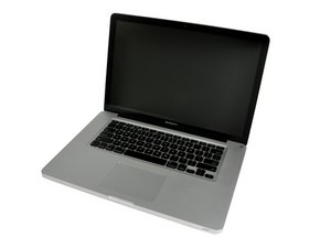
Released June 2012 / Core i7 processor with Turbo Boost / Up to 1 GB GDDR5 Video RAM

596 个问题 查看全部

Solder line in port on audio port's place

Block Image

Block Image

Hello,

A headphone tip broke off in my audioport, and after reading terrible advice on some forums I tried the superglue idea to remove the tip.. Resulted in my port being glued together.

Long story short, I found a company who thought it would fix my internal speakers if the audio port was removed from the Logic Board. Guess what, it didn't. It seems impossible to get a replacement part for the audiojack as well.

Now, is it possible to desolder the Line-In port and solder it on the audio port's place in order to fix my internal speakers?

I don't need the headphone jack to work persé, I just want my internal speakers to come back to life.

Greetings,

Marc
已回答! 显示答案 我也有这个问题

这是一个好问题吗?

得分 2
添加一条评论

1个答案

已选择的解决方案

schoutenmj, the Line In jack and the Audio Jack are different. Apple part number for the Line in jack is 514-0635 and the Audio Jack is 514-0671. Sure you could always try, but the biggest issues is that you may run into trouble soldering it twice and trying to make it fit. More room for error. If you do want to replace it, you can try and find a new jack or you can get it of an old board. The issue here is that it will require quite some skill to solder it properly. Take a look at the schematic. Pin 1 and pin 2 are normally closed, and open when you insert the jack. So if you remove the jack, your circuit will be open. Try to place a jumper from pin 1 to 2 to close that circuit.

Block Image

这个答案有帮助吗?

得分 3

3条评论:

Thanks for your reply, Oldturkey03!

Unfortunately, I'm not able to read schematics as I'm a total noob in soldering, but perhaps I can try to find someone who can and place that jumper you were talking about to close the circuit and make the speakers come to life!

完成的

Post an image of your logic board with your question. focus on the area where the audio jack was located. Post front and back images so we can show you at least where pin 1 and 2 are located. to add images to your question, use this guide 在已经存在的问题里加入图片

完成的

I'm not so fond of taking out my logic board myself, I'm not really handy with these small electronics (stuff will break if I touch it..!!)

So I guess I'll just have to find someone who won't and can solder it for me. :P

Thanks for your time and effort, Oldturkey03!

EDIT: I've posted some pictures of the backside, one with dramatically overflash but the holes in my logic board are properly visible there.

完成的

添加一条评论

添加你的答案

schoutenmj 将永远感激不已
浏览统计数据:

过去 24 小时: 0

过去 7 天: 0

过去 30 天: 1

总计 205